Decks without railing
Do I Need Railing On My Deck?
If your deck is somewhat low to the ground, you may have chosen not to install a railing. Unfortunately, this choice isn’t always wise due to safety concerns, as well as code violations.
In this blog, we’ll explore the reasons why it is in one’s best interest to install a railing and the decking codes to follow.
Decking Codes
If your deck is below 30 inches, a railing is not required.
With that said, if you choose to build a deck, even if it is only 24 inches off the ground, that is still high enough that even an adult could injure themselves. When you take your kids and pets into account, the risk is even higher.
Reasons People Decide Not to Install a Railing
Building a deck is not an inexpensive decision, so when someone is tasked with the decision to spend extra money on something they “don’t need,” like a deck railing, the choice seems obvious: save money.
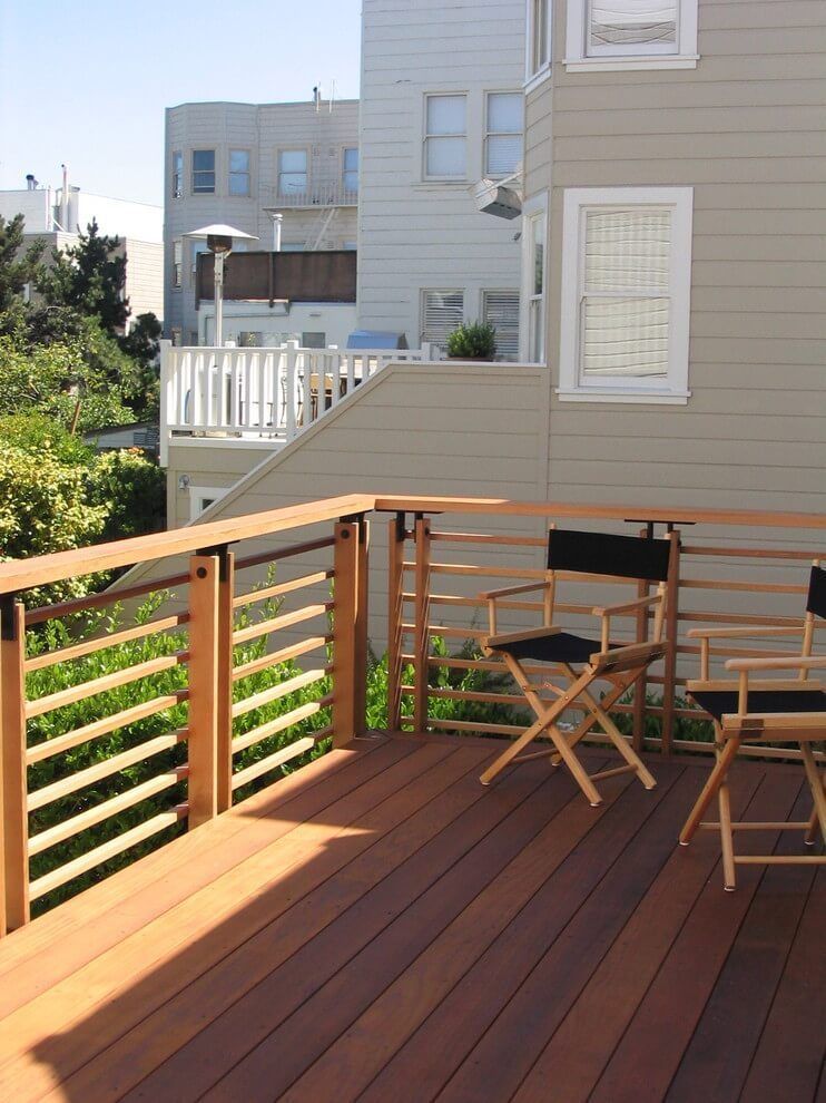
There’s also the aesthetic factor of not having a railing. For some, the look of uninterrupted deck space is what they want.
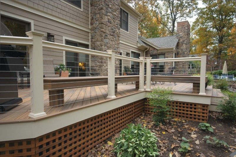
In addition, some people feel railings are difficult to install because their decks are an unusual shape. This shouldn’t be a concern, though. There are some great, easy-to-install railing kits available for decks with unorthodox shapes.
Why You Should Install a Railing
As previously mentioned, safety is the biggest concern when it comes to deciding whether or not to install a railing.
Railings can serve to protect children, pets, and even adults. It may seem like a short distance, but any fall can lead to broken bones or other injuries. Rather than being ever-vigilant when the kids are horsing around on the deck, deck railing helps give you peace of mind so you can relax and enjoy the view.
Taking away the safety aspect and just focusing on aesthetics, a railing can make your deck look much more expensive without adding a large sum to the grand total. Check out the large variety of railings available at Decks & Docks and add that finishing touch to your deck today.
What to Do if there Are No Requirements
Let’s say you have a deck that’s below 30 inches and there are no guardrail requirements by the IRC (International Residential Code). You could take the chance and go against the recommendations by the individual railing manufacturers. Keep in mind, if you do this as a contractor and someone hurts themselves due to faulty railing installation, they will be favored by a judge if they decide to sue. Ultimately, it’s always best to follow the manufacturer’s recommendations instead of cutting corners. Also keep in mind that there are deck railing height requirements, The IRC requires guardrails to be at least 36″ in height measured from the deck surface to the top of the rail.
There are deck railings that exist just to be decorative but which don’t serve a functional purpose. These aren’t the best idea because they aren’t truly functional. As previously mentioned, if you install a railing and someone gets hurt because it’s faulty, a lawsuit will most likely not go in your favor.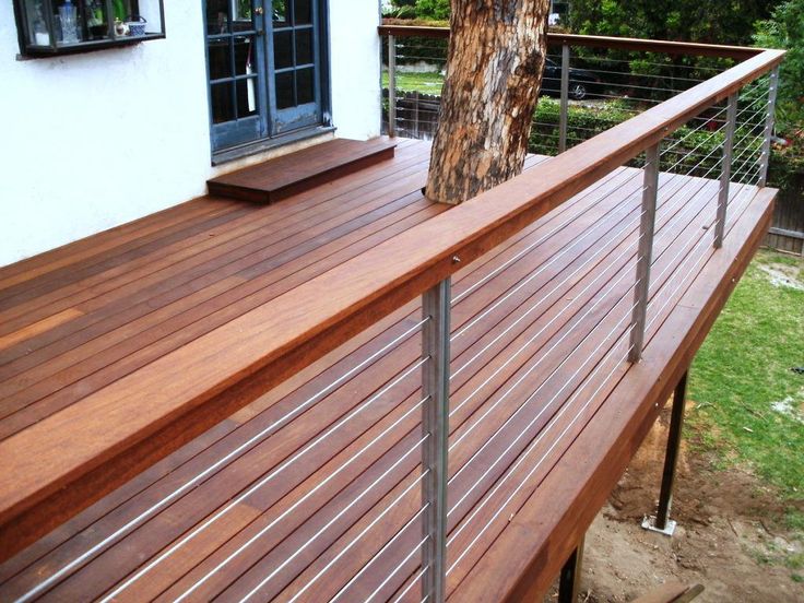
Codes to Keep in Mind
According to decks.com, a site maintained by Trex, your deck will be required to pass these tests during an inspection.
Uniform Load Test: The top rail of your deck must be able to withstand at least 125 lbs of force (applied vertically or horizontally).
Infill Load Test: This measures the strength of spindles, balusters, or any other load-bearing element between posts. An area of one-square-foot must be able to resist a force of 125 lbs.
Concentrated Load Test: The deck’s top rail must hold a point load of 200 lbs applied at three points: the mid-span, adjacent to a post, and on top of a post.
Types of Railings
Whether you want a modern, industrial, or traditional railing to enhance the look of your deck, Decks & Docks has something for you (plus everything you need to install it).
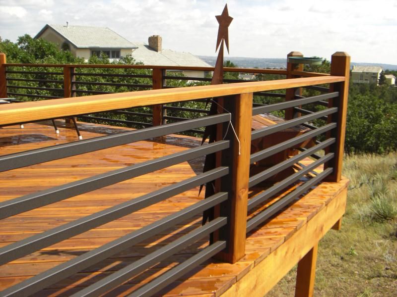
There are five types of railings—vinyl, cable, stainless, composite, and metal—and they each have their own benefits and style.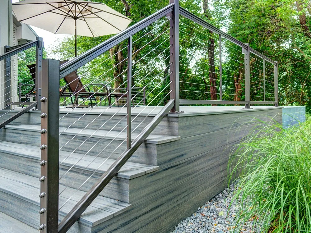
- Cable railing is great for those looking for a chic railing for their deck, as well as a railing that will not hinder any views. They’re versatile and can be used on decks, docks, and even interior spaces for a clean, utilitarian look.
- Stainless steel gives any deck a super sleek look. Some homeowners and builders expect stainless steel to be expensive, but it’s surprising how affordable it can be. Plus, stainless steel is made to withstand the test of time, making it a more durable and cost-effective choice in the long run.
- Aluminum railing is designed for those who like versatility and durability. With a variety of textures and colors available, you can find an option that truly exemplifies the style of your home. These railings arrive pre-assembled so you can enjoy them as soon as possible.
- Composite railing is the closest one can get to the look of real wood without the hassle of having to paint and stain and worry about splinters.
 It’s ideal for someone looking for a traditional look with less maintenance. Plus, composite railing is long-lasting.
 - Vinyl is a great choice for those looking for a low maintenance railing. It comes in many colors to match a new or already existing deck. Vinyl doesn’t show scratches like wood and doesn’t need to be painted like traditional wood decks. Vinyl’s durability makes it a cost-effective solution in the long run. It also provides a more traditional look for someone who’s going for classic deck design.
Decks & Docks is here for all of your decking and railing related needs. Call our friendly staff with any questions at 866-528-9663 and check out our gallery for inspiration.
The Maximum Deck Height you can have Without a Railing
I went to a friend’s house a while back to admire his new deck. This friend was very excited, especially by how much time he saved by not adding a railing. He’d made a point of building his deck so as to stay under the 30-inch requirement--which is the maximum deck height you can have without a railing. As we relaxed on the new deck with a couple of beers, my friend’s Shih Tzu dog came racing out of the house barking at a squirrel and skidded off the deck into the flower bed below. The dog was perfectly fine, but after we had stopped laughing--with relief--about it, I had to respond, “That wouldn’t have happened with a railing.”
Maybe you have plenty of lighting around your deck and you and your friends aren’t planning on falling off it anytime soon. But there may be other concerns as well, like pets, children, and even furniture. Gravity doesn’t stop working just because your deck is lower than 30 inches. A well-made railing is always the safer option, even if it’s not a long fall. On top of that, they just look better. I’ve found that railings give an outside structure a more finished look with better curb appeal. While most codes allow you to leave off the railings on decks lower than 30 inches, there are lots of reasons why you should still consider one.
Why Homeowners Go Without Railings
As my friend scooped up his dog, he mused on the fact that even though he’d built the deck to code, it still wasn’t as safe as it could be.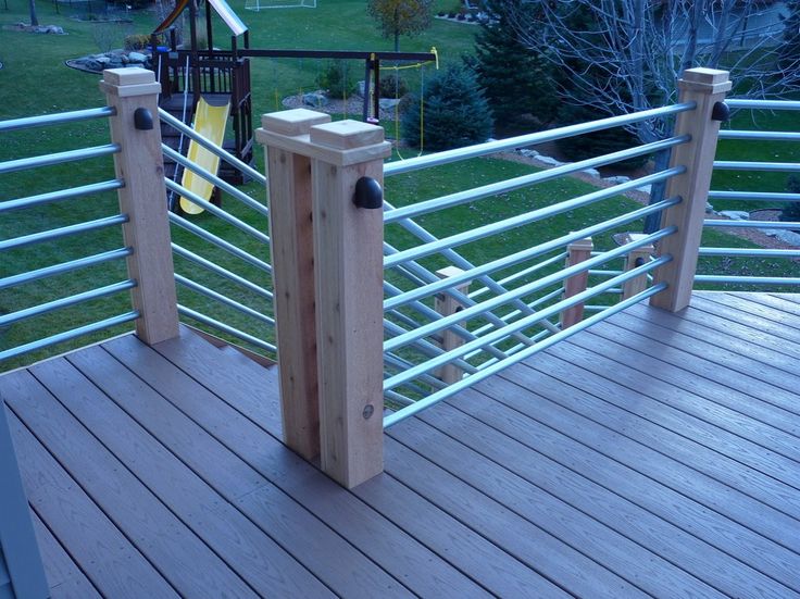 That’s a big lesson most new DIYers learn; just because you can do something doesn’t mean you should. Adding a railing to your deck can not only improve its safety but also your home’s curb appeal. Most often, I hear someone choosing not to add a railing for one of the following reasons:
- Expense: Some people skip the railing just to save money. But here’s the deal: going without a railing could eventually cost you money, too. The first time someone missteps and breaks an ankle is going to cost you. Or, if you avoid that, consider the cost to get rid of the critters that decide to move into the dark, enclosed space under your low-to-the-ground deck. Eventually, your choice to build low could cost you. It will probably cost more than it would to install a railing so you can build higher.
- Installation issues: The main reason that my friend avoided the railing was because the deck was oddly shaped, and he didn’t want to mess with installing a railing along its contours.
 But if he’d done a bit of research, he would have found complete, easy-install railing kits specifically designed to work with oddly shaped decks.
 - Increased code liability: If you install a railing on a deck that isn’t required to have one, the railing is still required to meet code. But this is another easy fix. Most trustworthy companies will only supply you with railings that meet all code requirements.
Those are the main reasons deck builders decide not to build a railing. But in some cases, you might build the deck under the 30 allowed inches, then find out you need to add one anyway. This happens a fair amount, for a number of possible reasons.
Why You Might Need to Add a Railing
One of the rules good builders go by is ‘measure twice, cut once’. It sounds easy, but there are a lot of different factors that could impact your floor-to-ground measurement. That number could change when the building inspector gets their tape measure out.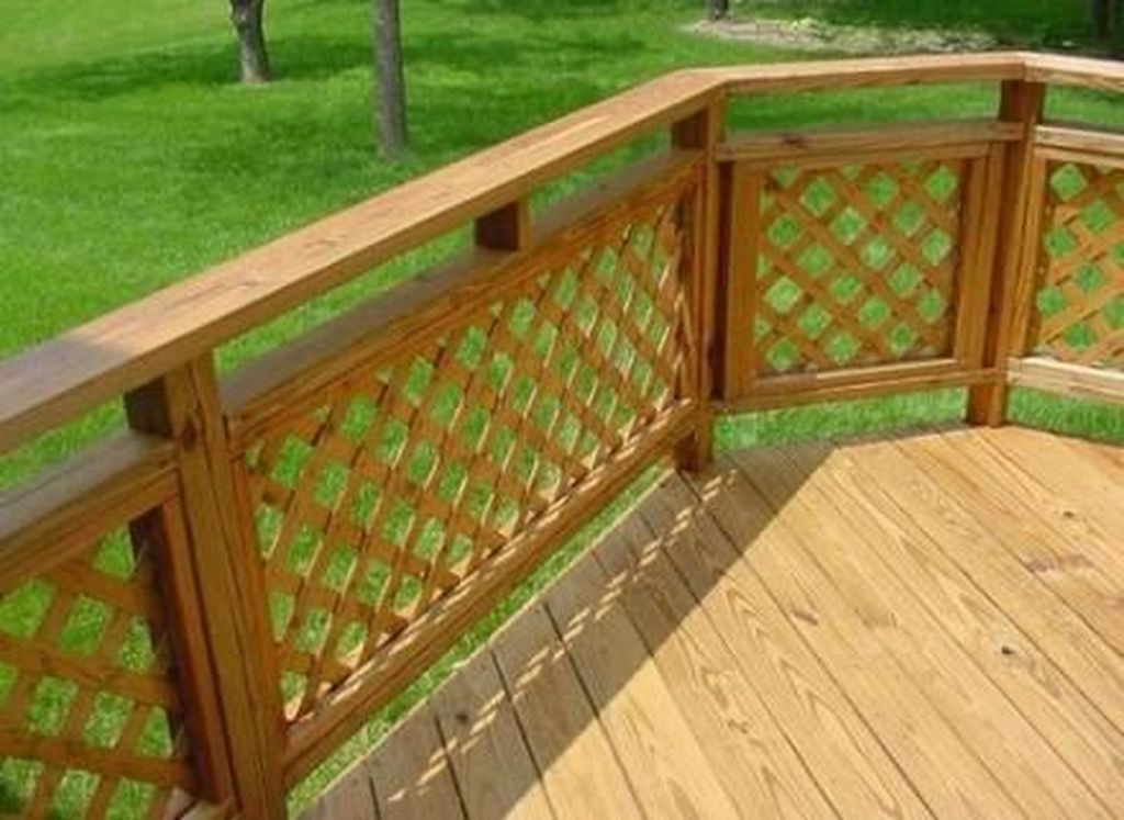 Sometimes, a DIYer will learn they must add a railing after the fact. It’s usually going to be for one of the following reasons.
- Land settling: If you’re building over dirt, that dirt could sink. Rain or snow could pool up under the deck, washing away the dirt and essentially lowering the ground. That alone can magically make your deck end up higher than 30 inches. If your deck is close to the limit, you’ll need to calculate in the cost of adding dirt because the ground may settle over time. That’s an ongoing cost, while adding a railing is a one-time expense that means your deck stays up to code no matter what the ground below it is up to. Dirt moves around, but your railing’s height will stay the same.
- Bad measuring: A common mistake for some is to measure from the bottom of the floor, when the measurement should include the thickness of the deck floor. If the wood is thick, this can throw off your measurement by a few inches.
- Slope: If you’ve built on a slope, in that you slightly tilted the deck to allow for water run-off, your actual above grade measurement may be a little bit higher than on other parts of the deck.

- Safety: A 30-inch fall for an adult isn’t great, but it probably won’t end in a broken bone. The same can’t always be said for small kids or pets. If you have either of those in your home, I’d highly recommend adding a railing.
If your deck is close to the 30-inch mark, or you just want to build a railing for safety, it’s not too late to add one if you have the right materials. The easiest way to install beautiful railings that meet code requirements is to purchase pre-assembled railing panels, rather than buying and putting together individual components.
What to Do When You Need to Install a Railing on Your Deck
The International Building Code says that your railings must be 36 inches or higher, but that isn’t the only consideration. There are specific regulations on everything from the distance between your balustrades to the screws used to anchor the railing. That’s why I recommend buying railing panels.
Fortress Building Products offers a lot of high quality, attractive railings in different materials and finishes. Cable railings have a sleek modern look and are usually very complicated to have installed, but Fortress® offers cable railing panels that are simple to purchase and to put in yourself. For a classic look, Fortress’ Fe26 steel railing come in a finish that mimics wrought iron but is much more durable, with multiple corrosion-resistant treatments like galvanization, a zinc precoat, a moisture-resistant e-coat, and a UV-resistant powder coating.
When buying from a company committed to continuous testing and dedicated to creating the most durable and safe railings out there, you can install entire panels that are already compliant with the codes for your region. That’s going to save you a lot of measuring and frustration. These railing panels come with easy-to-install hardware and brackets that are compliant with IBC capacity requirements as well. A pre-assembled railing panel is a great choice if you need to finish off your deck with a safe and code compliant railing, but not all are created equal.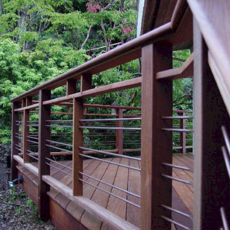 It’s best to find a railing manufacturer that goes above and beyond the code requirements to create a railing that’s as safe and durable and long-lasting as possible. In my experience, that’s what Fortress does. And if you’re working on your deck or on other projects around the home, Fortress Building Products sells other, equally safe, durable, and innovative products like decking, fencing, and ornamental hardware.
Open deck and railings on transport ships
Open decks on transport and cargo ships pose a real danger to the integrity of the hull structure in heavy seas, so various railings are provided.
ContentHide
- Participation of bulwarks in operation together with the main hull
- Guard rails
- Wave breakers
- Movable connections made to reduce stress concentration
Bulwark engagement with main hull
Steel plate bulwarks on riveted ships are firmly attached to the side plating along the entire length of the open areas of the upper decks on most cargo ships.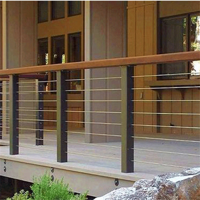 To drain water splashing through the bulwarks, holes were cut in the upper decks, called storm porticos (Fig. 2).
1 - upper deck bulwark; 2 - wave baffle at the end of the tank; 3 - railing; 4, 5 - bulwark on the tank with a visor
At present, on large welded ships in the middle part of the length of the ship, in order to avoid the participation of bulwarks in the general longitudinal bend, together with the main hull, it is supposed to arrange continuous longitudinal slots separating the sheerstrake bulwark sheets.
Fig. 2 Scheme of the general position of the bulwark movable joints on ships of the Bezhitsa type.1 - bulwark; 2 - mobile connection; 3 - sliding connection on rivets; 4 - slot
Such bulwarks appeared on ships with welded hulls after it was discovered that it was welded bulwarks, in contrast to riveted ones, that became the source of cracks that spread to the main hull. To avoid this, the bulwarks were cut off from the side plating and the risk of crack propagation from the bulwark to the main hull was prevented (Fig.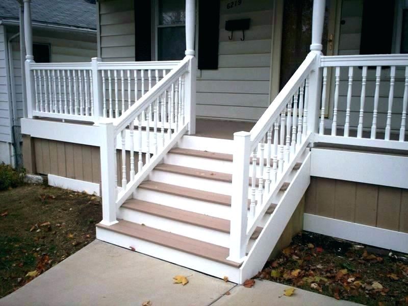 3). However, as a result of this, the local strength of the bulwarks significantly decreased and their damage increased.
1 - movable connection at the adapter bracket; 2 - intermediate movable connection
Later, the device of movable connections in the bulwarks at the transitional brackets of all superstructures (Fig. 4) and additionally several movable joints in the gap between superstructures (Fig. 3, 5) began to be used. At the same time, it was possible to rationally use bulwarks as strong ties, especially if it was necessary to increase the upper girdle of an equivalent beam; this was not done. Together with continuous longitudinal coamings, bulwarks can even play a positive role in increasing the strength of ships.
Fig. 4 Transition of the superstructure wall to the bulwark.1 - longitudinal wall of the superstructure; 2 - transverse wall of the superstructure; 3 - transition knitsa; 4 - board; 5 - transverse bulkhead; 6 - sheerstrake; 7 - upper deck; 8 - beam; 9 - frame; 10 — rack transverse bulkhead; 11 — bulwark
Bulwarks with lids (see Fig.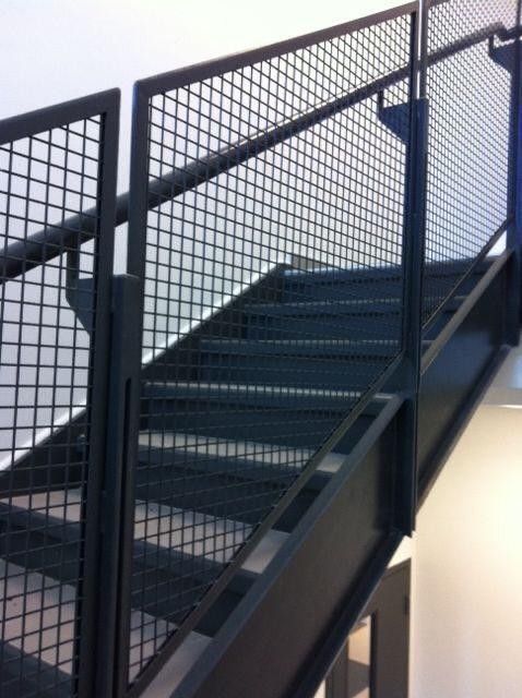 2), closing the storm ports by the pressure of the waves from the outside, provide a runoff of water splashing onto the deck, reduce flooding due to some increase in the freeboard height. The decrease in the local strength of the hanging bulwarks caused their frequent damage, especially on timber carriers. On ships carrying heavy cargo on the upper deck, bulwarks reliably secure the deck cargo with lashings (fastening cables), and for timber carriers - also the support of the walls, contributing to the formation of a deck timber caravan. Fastening heavyweights to bulwarks is more reliable than to eyelets and butts welded to the deck.
Bulwarks firmly attached to the sheerstrake are in all respects more reliable in operation, so there is every reason for their widespread use on new ships.
Fig. 5 Sliding joint in the middle of the bulwark length.1 - bulwark; 2 - vertical rib; 3 - gunwale; 4 - safety bar covering the section of the bulwark; 5 - section of the bulwark; 6 — rack bulwark; 7 - horizontal rib; 8 - deck; 9— board
The bulwarks are a sheet structure supported by uprights (buttresses).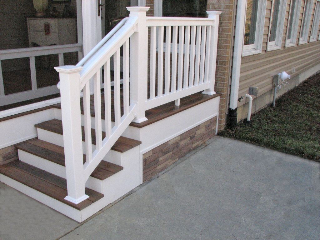 They break away from the deck stringer in the area of movable joints, requiring special attention during design (Fig. 6).
1 - bulwark; 2 - gunwale; 3 - deck; 4 - board; 5 - longitudinal coaming; 6 - longitudinal beam; 7 - beam
In addition, holes are made in the bulwark sheets for mooring fairleads (fig. 7) and scuppers for draining water from the inside. Various devices are hung on them in the form of bollards, ducks and rollers for cables (Fig. 8) to control the rigging.
Fig. 7 Construction of the bulwark at the fore end of the Far East whaling base.1 - gunwale; 2 - step; 3 - sheerstrake; 4 - clus; 5 - pillar
Bulwarks protect the open decks of both the main hull and superstructures, and especially on those ships where during cargo operations dynamic loads from impacts caused by moving cargo can occur. Under these conditions, the lifelines may be damaged.
Fig. 8 Reinforcement of the bulwarks in the area of the transitional knitsa at the whaling base "Far East" The strength of the bulwarks is still endangered by various holes, as well as the wrong choice of the location of expansion movable joints, bulk of ships moored to the side and parking in rough conditions.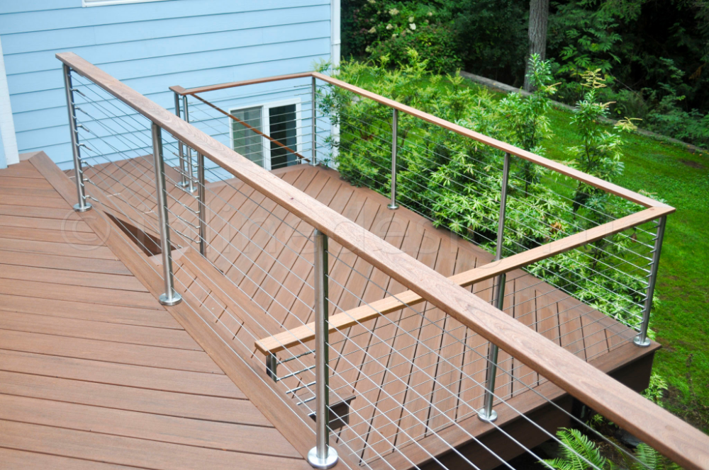
Calculations show that if the bulwarks are designed so that they take full part in the overall buckling, then the stresses in their upper fibers increase markedly compared to the normalized stresses in the upper deck. In order for the stresses in the bulwark not to exceed the stresses in the upper deck, the area of the latter will need to be increased by 6-11%. Therefore, it is more expedient to make bulwarks from high-resistance steel, as has long been done on mixed navigation ships for continuous longitudinal coamings.
However, for modern ships with continuous coamings and bulwarks attached to the sheerstrake without increasing the deck area, the maximum stresses in the upper fibers of the bulwarks and longitudinal coamings will not exceed the rated stresses in the upper deck. Despite the apparent simplicity of bulwark designs, they have to work in difficult conditions, and the lack of reliable regulatory documents for the design leads to numerous errors leading to damage and causing frequent repairs.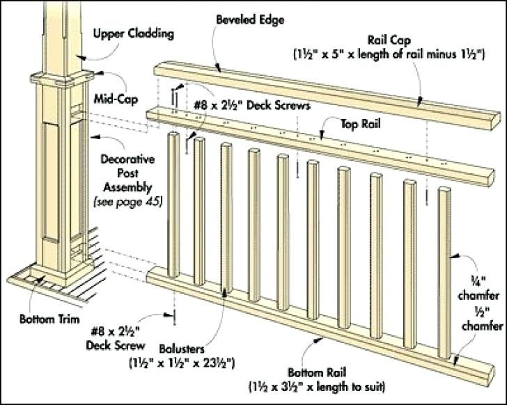
To develop reliable recommendations, it is possible to use the results of many years of research conducted at the Department of Ship Design of the Far Eastern State Technical University. The results of these studies can be found in the specialized literature. The same sources provide the results of experimental studies carried out during numerous voyages across the Pacific Ocean during severe storms.
See also: External skin and its reinforcing set
Weld horizontally along the upper free edge of the bulwark gunwale (railing) from bulbous strip beams. It provides the strength of the bulwark under the action of transverse loads on it and serves as a convenient support for those moving along the upper deck.
Guardrails
Guardrails (Fig. 9), which replace bulwarks, are not very strong and are not designed to take large transverse loads. Their role is limited to ensuring the safety of people when they move along open decks at the boundaries that limit open surfaces.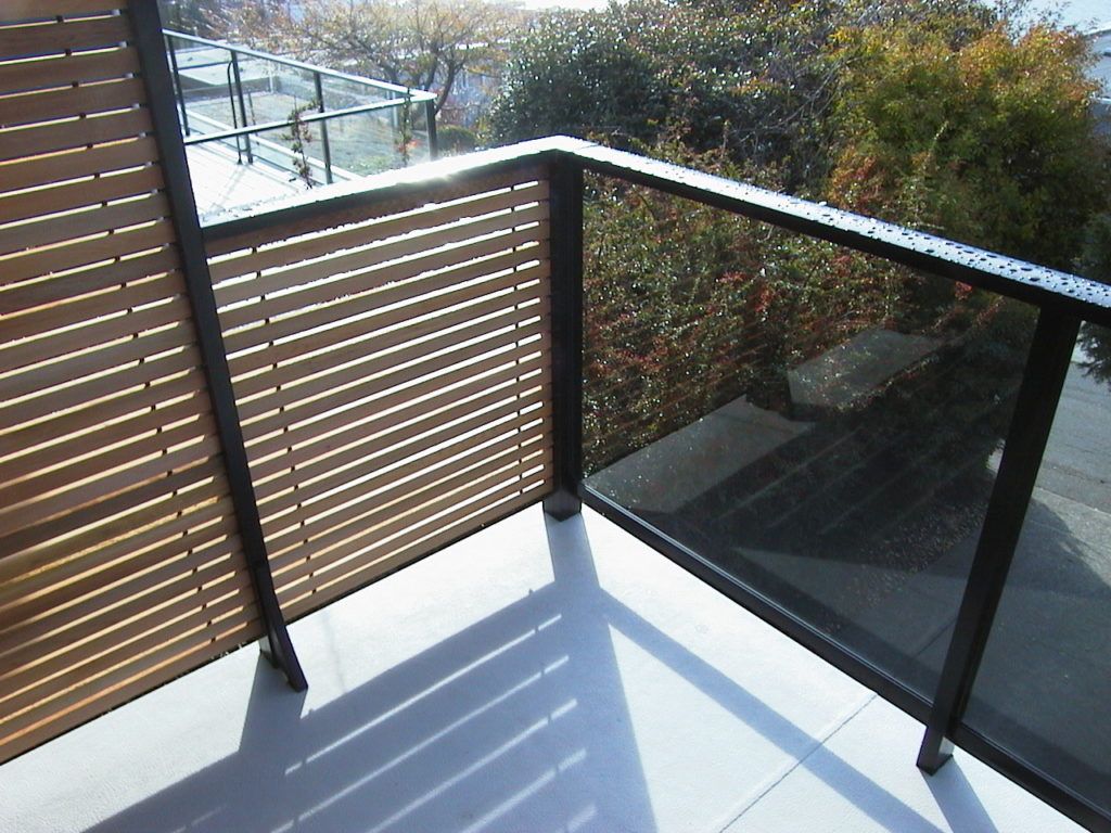 Railings are also installed indoors to prevent people from falling off platforms and ladders. Handrails are often fixed to the vertical bulkheads of corridors, facilitating the movement of people during pitching.
Guardrails are constructed of vertical posts with several extensions along their height with round holes through which thin bars, pipes or chains pass. These posts are installed at a short distance from each other and are firmly flanged to the deck sheets or to the protruding edges of the vertical sheets forming waterways at the edges of the surfaces. In some areas, railings are made removable (see Fig. 9) in order to dismantle them and create free passage. Such walkways are used to install gangways or ladders to move people to berths or neighboring ships.
The decks of tankers are fenced with lifelines, and the movement of people along the vessel occurs through special passages raised above the deck, also protected by lifelines.
Wave breakers
In order to prevent the impact of waves rolling onto the upper deck, wave breakers are installed in the bow (on the forecastle) (Fig.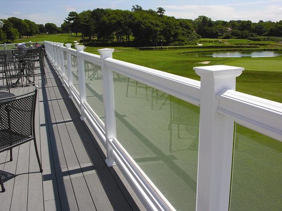 10). These are sheet overlaps, supported by a vertical and horizontal set. The result is a strong transverse structure capable of absorbing large shock loads from waves and preventing damage to deck cargo and machinery.
Wave breakers have been most widely used in recent years on container ships: they prevent containers from collapsing. The height of these reflections on large ships reaches three meters.
The absence of wave breakers on the forecastle of timber carriers during a storm causes the timber to shift on the deck and damage to the cargo mechanisms. So, for example, when conducting experiments during a strong storm on a timber carrier "Kungur" shifting logs destroyed the electric winch controller and damaged the bulwark. It seems appropriate on all timber carriers at the ends of the short forecastle, as well as on container ships, to install wave breakers, resting them on the high bulwarks of the forecastle and long transitional knees going to the bulwarks of the upper deck behind the forecastle.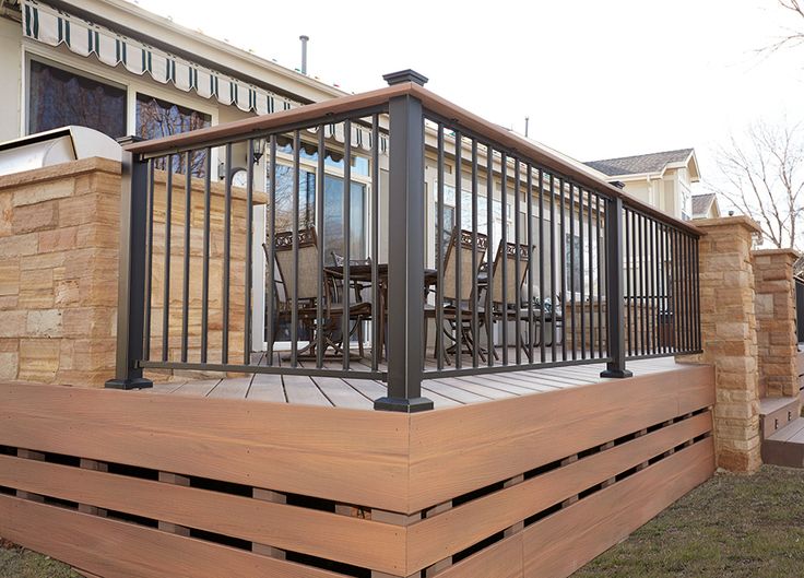
In conditions of sailing in winter in the northern seas, wave breakers, together with high bulwarks on the forecastle and transition brackets, help to reduce freezing, which always causes a significant delay in the start of cargo operations after arriving at the port. The team spends a lot of time and hard work on the fragments of ice heaps. Freezing and subsequent chipping are often accompanied by damage to the mechanical closures of cargo hatches and deck structures.
Breaking ice with heavy hand tools increases wear on structures and destroys paintwork. When designing structures, special attention must be paid to this issue and high long transition brackets should be installed starting from the upper edge of the wavebreaker, and a continuous, high, strong bulwark should be mounted on the tank, ensuring a quick drain of water from the tank through large holes in the wavebreaker, using them for installation ladders.
Sliding joints to reduce stress concentration
Longitudinal walls of superstructures with hanging bulwarks and railings must always be gradually reduced to nothing in the form of transition brackets (see Fig.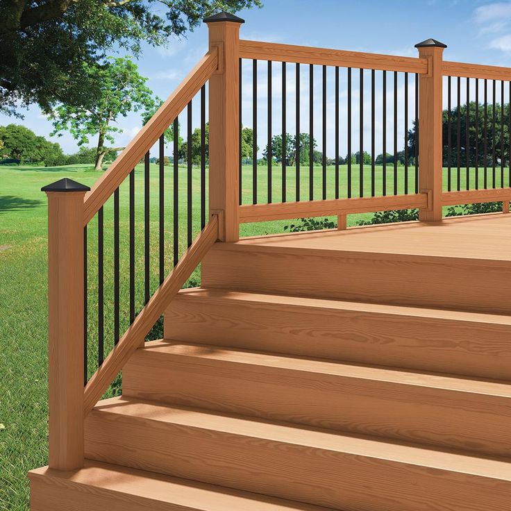 3) and welded to the upper edge of the sheerstrake that protrudes above the deck. The bulwarks must be separated from the edges of the transition knees using movable joints. In the interval between the movable connections at the superstructures, it is necessary to perform several more movable connections. The presence of a longitudinal slot and movable joints in the bulwarks significantly reduces the degree of their participation in the overall longitudinal bend together with the main body.
Bulwarks, rigidly attached to the sheerstrake, together with the transition brackets, are a continuation of the longitudinal walls of the superstructures, being one with them, and together with the main hull participate in the general longitudinal bending and, of course, do not need the device of movable joints.
Previous articles have dealt with movable connections widely used on modern ships in hanging bulwarks. However, the expediency of using mobile connections is not limited to this; their arrangement can contribute to the ennoblement of many intermittent connections of the ship's hull.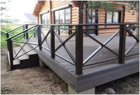 Despite many years of efforts to reduce the concentration of local stresses that manifest themselves during operation and pose a serious danger to the strength of hull structures, nodes with large local stresses remain in the hull to date. These nodes continue to be the source of initial cracks, which, under difficult operating conditions, cause serious accidents, often threatening the death of the ship.
Under normal ship operating conditions, cracks that appear usually propagate slowly and do not reduce the reliability of the hull. However, exhaustion of the fatigue strength resource can unexpectedly occur in severe storm conditions in structures with increased stresses and cause rapid propagation of initial cracks over long distances. This can occur under conditions of rapid exhaustion of the residual fatigue life of structures that have successfully operated under normal operating conditions. Under extreme conditions of dynamic loading, the residual fatigue life in some nodes with high local stresses, even with a small number of alternating loads, can be fully used (low-cycle fatigue) and can cause hull failure.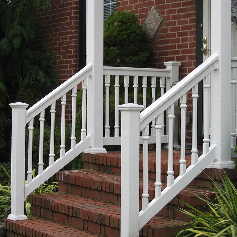
Initial cracks almost always occur at high stress concentrations, which still exist in many hull structures. Therefore, it is necessary to achieve an all-round reduction in the stress concentration by new methods. One of these methods is the creation of mobile connections. This method has been successfully used for many years during the elimination of damage to the structures of ships of the Far Eastern Russian shipping companies, whose ships operate in the northern seas of the Pacific Ocean.
Modernized structures have been monitored for several decades, but mobile connections are not regulated by the Rules and Norms.
The moveable joints were initially used only after several repeated unsuccessful attempts to use traditional methods of reducing local stresses, if they did not give positive results and damage in the modernized structures occurred again.
As is known, the traditional methods of reducing stress concentration usually consist in redistributing these stresses to neighboring structures and in reducing the stiffness of nodes.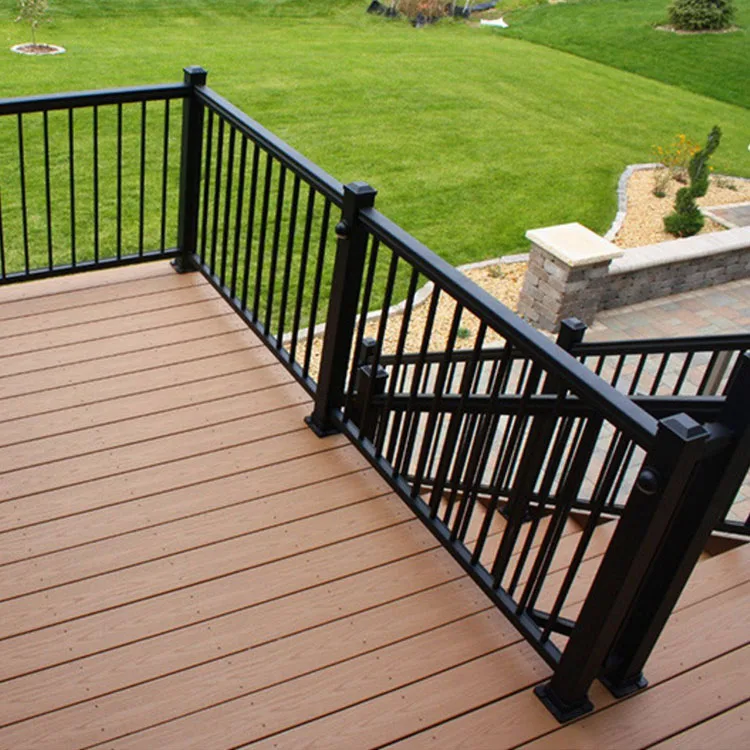
However, a radical reduction in stress concentration can be achieved only due to the compliance of the created structures, as was the case in riveted structures. Sliding of riveted joints under high loads contributes to the redistribution of stresses and a decrease in their concentration peaks. This also contributes to the elimination of the volumetric stress state in the region of rigid points. Experiments on old riveted ships confirmed this. Indeed, in intermittent connections of riveted ships, water flow in the seams was often observed, which indicated their displacement, as a result of which the stress concentration decreased, and especially under the action of dynamic loads. For this purpose, riveted seams are still used in welded railway bridges.
11 shows an example of damage to structures caused by displacement of rivet joints.
Fig. 11 Construction of the bulwark of a riveted vessel.1 - deck; 2 - board; 3 - gunwale; 4 - bulwark sheet; 5 — rack bulwark; 6 — angle deck stringer; 7 - butt joint of sheets; 8 - square-short; 9 - scupper; 10 - crack
On riveted ships, movable joints were made in superstructures - deckhouses in order to exclude them from the general longitudinal bend together with the main hull.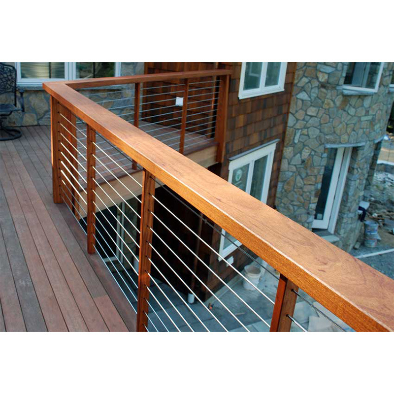 Until now, the regulatory documents contain recommendations for the implementation of movable connections in deckhouses, which, if properly designed, play a positive role, however, in the area of their termination below the deck, a new intermittent connection appears (Fig. 12), which requires attention.
1 — hull deck; 2 - superstructure deck; 3 - Expansion joint
Rigid points are formed in the corners of superstructures and deckhouses, which are sometimes called knife supports , causing volumetric stresses in complex structural units with the formation of cracks. In addition to the corners of deckhouses, cracks often occur at the intersections of the longitudinal underdeck beams of the frontal walls of superstructures and deckhouses. This is observed when the frontal walls are located even at a great distance from the midship. Demand attention to the design of decorative sheathing, enclosing the passages at the sides along the cuttings under the superstructures.
It will be interesting: Design and calculation of deck slabs
There are recommendations to replace the point nature of the transfer of forces at rigid points with a high concentration of stresses with a linear one, as is done with the help of high transitional brackets at the ends of the superstructures, going from side to side. However, the extension of the walls of deckhouses, their internal longitudinal bulkheads and the installation of knees in the areas where karmings intersect with the front walls of superstructures and deckhouses are objected to because they will interfere on or below the deck. In the meantime, such knees are not put up at all and the cracks are welded up, and at the first strong storm they appear again. In practice, sliding joints with rivets were successfully used for cutting angles (Fig. 13), and for crossing carlings with transverse walls of superstructures, expansion joints with a slot open below deck (Fig. 14) were successfully used.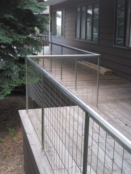
1 - upper deck plating; 2 - frontal wall of the cabin; 3 - side wall of the cabin; 4 - vertical strip; 5 - square; 6 — overhead strip
For many years, the work of movable joints of various types as part of the hull has been studied at the Far East Industrial Institute (FEGTU). On ships in stormy conditions, experiments were carried out with various designs of mobile connections, and for many years observations were made of various options for mobile connections when ships returned from navigation.
It should be noted that the replacement of point-to-line force transfer recommended by the Register somewhat increased the fatigue life of intermittent links, but after severe storms, damage reappeared. This was also the case when conducting experiments while sailing across the Pacific Ocean on a container ship in a hurricane.
Installing thicker HRP weld-in plates increased fatigue strength somewhat, but not enough.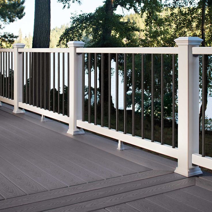 Vibration as a result of large dynamic loads, which caused large amplitude oscillations of the body, caused repeated damage as a result of low-cycle fatigue.
a - with a longitudinal dialing system; b - with a transverse typing system.
1 - deck; 2 - frontal wall; 3 - carlings; 4 - pillers; 5, 6 - zone of slots in carlings and beams; 7 - beam
Even the installation of large knees at the ends of high longitudinal coamings did not relieve the high concentration of local stresses on large bulk carriers "Ob" and "Yenisei" , built in South Korea (Fig. 15), and on the Japanese bulk carrier ( Fig. 16 and 17).
Fig. 15 Separation of the end of the longitudinal coaming from the deck.1 - deck; 2 - coaming with a transition bracket; 3 - additional knitting; 4 - crack; 5 — support for hatch covers; 6 - wave baffle; 7 - belt of transition bracket
If the ends of the longitudinal coamings with brackets were with movable joints along their lower edge, then this would dramatically reduce the stress and the likelihood of cracks.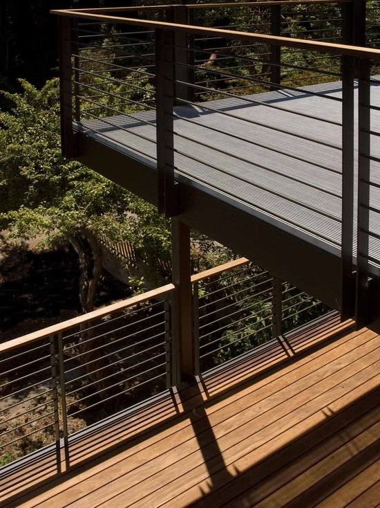 Similarly, in the 50s in Vladivostok, the issue of reinforcing ships was positively resolved "Liberty" Far East Shipping Company. This completely eliminated the appearance of cracks at the ends of the longitudinal coamings at the corners of the cargo hatches, which had abruptly breaking coamings.
All activities related to the use of mobile connections in the Far East were carried out with the permission of the Register's Pacific Inspectorate. At one time, the Main Department of the Register imposed a ban on the use of mobile connections due to the lack of calculation justifications. At the same time, it was noted that the ban “may be lifted by specifying the conditions for the use of structures with an open slot” (see Fig. 14). However, before the advent of the aforementioned ban, mobile connections were already used on many emergency ships.
Fig. 16 Stresses along the free edge of the transitional knee of the longitudinal coaming, height:a — 1,750 mm; b - 1000 mm.
1 - deck; 2 - transverse coaming; 3 - transitional knitsa
The issue of ensuring the reliability of various designs was resolved at low material costs. The modernized designs proved to be quite efficient in the most difficult operating conditions.
The movable joints recommended by classification societies have some drawbacks. First of all, this concerns the movable joints of the bulwarks with a continuous longitudinal slot, which reduce the transverse strength and form intermittent bonds. This is a consequence of the attraction of sections of bulwarks between adjacent movable joints to a common buckling. As a result, there is a separation of the extreme racks, near the movable joints. Until now, a methodology has not been developed for determining the required number of connections for ships of different sizes and for determining the forces that cut off the extreme bulwark posts located near the expanders.
It is of interest to compare two methods of eliminating damage in the area of crossing the frontal pillar of an average long cabin with high carlings on the upper deck of two large expeditionary ships of the type "Abkhazia" .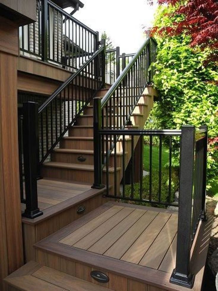 These ships were used in long heavy ocean voyages and in the northern seas of the Far East.
1 - deck; 2 - longitudinal coaming; 3 - transverse coaming; 4 - transition knitsa; 5 - deck tank; 6 - crack; 7 - weld
On both vessels, after repeated attempts to eliminate the re-occurrence of cracks in the deck plates using traditional methods, movable joints were made (see Fig. 12), which made it possible to get rid of hard points. After making movable joints on one of the vessels, the design organization, citing the complexity of the repair, used the installation of large knees on another vessel of the same type. It was a cheaper traditional method of reducing local stresses by redistributing them over a larger area with the help of knees.
After a long, hard voyage, the ships were inspected. It turned out that the mobile connections performed their positive role, while the use of traditional methods caused repeated damage.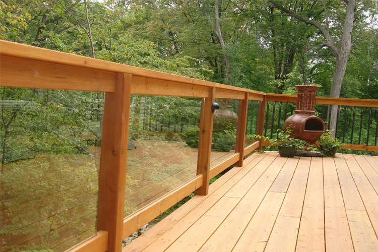 After that, mobile connections were made on the second vessel. Years of voyage by both ships no longer caused damage to the upgraded designs.
Movable joints in the practice of world shipbuilding have received some distribution at the very beginning of the transition to welding in the corners of the cuttings.
Three different types were used. In two cases (see Fig. 11, a, b ) the structures reduced the concentration of local stresses, but the cracks reappeared. It turned out that in the first case, a vertical strip welded to the deck and riveted to the wheelhouse prevented the longitudinal movement of the ends of the wheelhouse with a general longitudinal bending of the vessel and cracks appeared in the weld. In the second case, cracks appeared at the apex of the square as a result of fatigue when the shape of the corner changed.
The most reliable connection for the corners of deckhouses turned out to be a connection with a strip, but always welded horizontally to the deckhouse and riveted to the deck. In this case, the ends of the cabin will be able to move in the longitudinal direction due to sliding in the riveted seam.
Suggested reading: Hull structures of transport vessels for ice navigation beams (see fig. 14). FEM calculations confirmed the feasibility of this measure to reduce the stress concentration. In the place where there was a cruel point, there was no stress concentration. The stresses at the ends of the slots turned out to be somewhat increased, and to reduce them, the ends ended in small round holes, which, according to current practice, may not be reinforced. It is also important that the slots are located in enclosed spaces below deck. Hot sale tempered glass railing deck decking balustrade railing glass system Deck glass railing system for indoor or outdoor more and more popular and more popular and more popular and popular human reason easy to clean, good vision and can decorative buildings are more beautiful. Our advantages 1. Competitive price of glass handrail for stairs 2. Lead time: 2-4 weeks (normal products) should be classified as quality control as below 4. Services Quick Response Detailed design and technical support from design to delivery Advising on material solution at the design stage 5. Project advice: rich reference to international projects 1500 6. High production capacity ----Average production capacity 20000 sets Commercial term 92002 hot sale tempered glass railing deck deck balustrade handrail for glass railing system 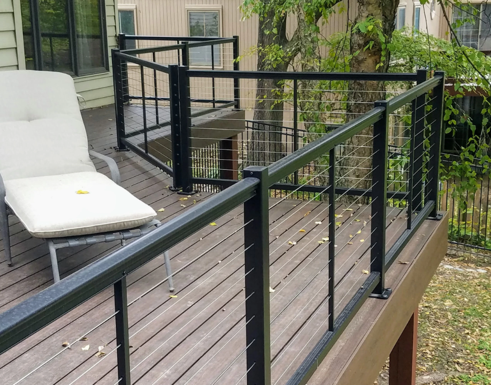 If you would like more bright and better eyesight, you can choose transparent glass balustrade, if you need light transmission, but also protect legal, then choose acid etched frosted glass railing, if you want more colofol and beautiful look, you can choose color pattern glass baluster.
 product name Advantage This is our classic railing type.