Clearing tub drains
5 steps to stop slow emptying |
When you purchase through links on our site, we may earn an affiliate commission. Here’s how it works.
(Image credit: BC Designs/Darren Chung)
Blocked bathtub drains are a common issue that few households escape, particularly when there are long-haired people in residence. Plumbers take time and money, so it’s only natural that you might prefer to learn how to unclog a bathtub drain yourself.
Hair is by far the worst bathtub drain-clogging offender, alongside soap build-up and residue from bath oils and conditioner, so this isn’t as off-putting a job as unclogging a toilet. However, if your bath has drained slowly ever since it was first installed, the issue is likely to be down to the gradient of the pipework beneath or a more serious sewerage issue, which is when you’ll need to call in a professional.
This guide will tell you how to unclog a bathtub drain in simple, expert steps; you can take similar steps to unclog a shower drain.
How to unclog a bathtub drain
Prevention is often better than cure. ‘If you find your bathtub is constantly getting clogged, then make a few changes to stop it happening again,’ says David Cruz, plumbing expert at MyJobQuote . ‘A simple strainer will prevent hair clogging the drain. And regular drain cleaning with a ready-made cleaner or even just hot water can help keep soap residue at bay.’ It’s worth adopting the same tactics to avoid the need to unclog a sink, too.
If you are currently experiencing a blocked bathtub, the experts recommend simple bathroom cleaning tips are often the best way to deal with the problem. Here’s how to unclog a bathtub in five steps – we’ve ordered them by ease, so work through step-by-step until your bath empties in a timely manner.
You will need:
- Sink plunger (we like this one from Amazon )
- Bicarbonate of soda and white vinegar
- Pluming snake (we like this one from Amazon )
1.
 Remove obvious obstructions
If you have a traditional drain stopper on a chain, accessing the drain opening on your bathtub will be a breeze. However, most modern baths support some form of integrated drain stopper – be it pop up, click-clack (a.k.a. toe-touch) or trip-lever. In this instance you will need to remove it to gain better access to the drain. The majority screw off, but some may require a screwdriver to pop the drain stopper.
Once you have taken the drain stopper out of the equation – and you may find a clog of hair/gunk comes with it – take a good look down the drain, using a torch if required. If you can see any obvious obstructions, use your fingers, small tongs or a wire coat hanger to drag them free.
2. Boil the blockage away
Assuming there is no standing water in your bath, the next easiest solution for unclogging a bathtub is the good old boiling water trick. ‘Pouring boiling water down the drain will help you get to the areas that may be out of reach. Boiling water is ideal for clearing grease and soap that has stuck together – the heat will activate it and help get things moving,’ explains Chris Wootton, Managing Director, of cleaning service Poppies .
Just a liter or so of boiling water should suffice. Once it has cleared, try running the faucet to see if things have speeded up. If not, it’s worth trying one more kettle full before moving on to step three.
3. Use a plunger
Before using a plunger you will need to plug the bath’s overflow to create the necessary vacuum. Most overflow covers screw off, then you can simply plug the hole with a damp face cloth or large slab of putty (like Blu Tack).
‘To execute the plunger technique properly, remove the drain stopper and fill the water up by a couple of inches. Take a sink plunger, not a toilet plunger, and place this directly over the drain before pumping it up and down a few times, taking pauses to see if the water begins to drain,’ says Trinity Owhe, Design Expert, Victorian Plumbing .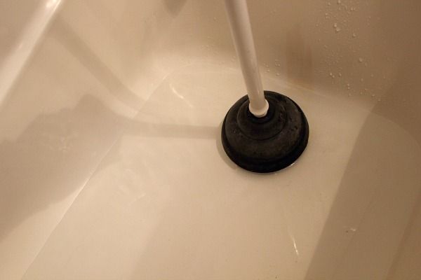 ‘Repeat this a few times until, with luck, the blockage is gone.’
4. Add baking soda and vinegar
Cleaning with vinegar and baking soda is a good way to clear a blockage in a bathtub drain.
‘Baking soda and white vinegar are a great home remedy for unclogging a bathtub drain. Pour some bicarbonate soda into the drain and let it sit for 15 minutes before pouring white vinegar down the drain,’ says Trinity Owhe, Design Expert, Victorian Plumbing.
‘The chemical reaction that occurs creates a strong foam-like substance that might dislodge any blockages and will also help neutralize unpleasant odors. Once the mixture stops fizzing be sure to rinse this away with water,’ she adds.
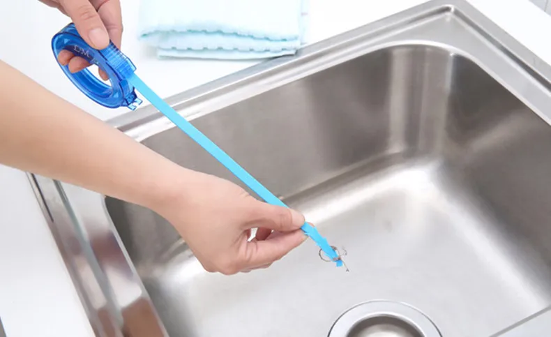
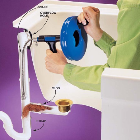
5. Invest in a plumber's snake
If your blockage is still refusing to budge, it’s time to tool up and learn how to use a drain snake or one of the range of tools, readily available from hardware stores or online, designed to delve deeper into your drain. Plumber’s snakes, hair snakes and long, flexible pipe-cleaners are all brilliant for breaking through blockages further down the pipework underneath your bath.
‘A metal plumber’s snake that is about 9ft long is best for accessing any obstructions that can’t be removed by hand. They’re easy to use and very effective,’ says Ben Chalk, Chartered Construction Manager, GIR Services .
(Image credit: Future PLC/Linda Clayton)
What can I pour down my bathtub drain to unclog it?
Boiling water should be your first port of call. ‘Baking soda and vinegar are also great natural alternatives to chemical solutions. Pour a cup of baking soda down the drain, wait a few minutes for it to set, then pour a cup of white vinegar down the drain,’ advises Chris Wootton, Managing Director, of cleaning service Poppies.
‘The mildly acidic solution should break down more severe clogs and following up by pouring boiling water down a few hours later should help clear any lingering debris. In the event this doesn’t work, you may need to resort to chemicals or unblocker – there are lots of reasonably priced and effective drain unblockers on the market,’ adds Chris.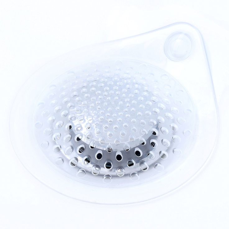
Linda graduated from university with a First in Journalism, Film and Broadcasting. Her career began on a trade title for the kitchen and bathroom industry, and she has worked for Homes & Gardens, and sister-brands Livingetc, Country Homes & Interiors and Ideal Home, since 2006, covering interiors topics, though kitchens and bathrooms are her specialism.
5 Tips for How to Unclog a Bathtub Drain
How-To,
When your shower or bathtub drain is clogged, it can cause major headaches. As a homeowner, it’s important to know how to fix a clogged bathtub drain so you can get back to your daily routine.
Read on for a list of five tips to help you unclog your tub to let the water flow freely once again.
1. Boiling Water
Shampoo and soap can cause a gunky buildup to clog your bathtub drain. To combat the problem, boil a pot of water on the stove, and slowly pour it down the drain.
While this tip might not work for all types of clogs (such as matted hair), the hot water can dissolve most soaps fairly quickly. Try this method first to see if it unclogs the drain and if not, it’s time to move onto another method.
2. How to Fix a Clogged Bathtub Drain with a Plunger
A plunger is one of the most popular tools to prevent bathtub clogging. How successful you are will depend on the nature of the clog as well as the design and size of your drain.
Take a plunger and add some water to the tub before you start to plunger vigorously. A small amount of petroleum jelly around the rim of the plunger can help to create a better seal.
3. Baking Soda and Vinegar
If you’re not a fan of using chemicals, this all-natural solution may help to unclog a bathtub drain. Start by pouring one cup of baking soda down the drain and let it settle for at least five to 10 minutes.
Next, pour a cup of white vinegar down the drain and allow the mixture to work its magic. You may need to finish by pouring some boiling water down the drain, but this method can work well for mild clogs as the baking soda and vinegar activate to dissolve icky buildup.
4. Manual Removal
A more aggressive way to learn how to fix a clogged bathtub drain is to simply remove it by hand. You may want to wear a pair of latex or rubber gloves before you start the process.
Remove the drain cover (look for any screws) and then look down into the drain to see if you can identify the clog. If you notice hair and other drain-clogging materials within reach, simply use your fingers to try and pull out as much as possible.
5. Try a Plumber’s Snake
A plumber’s snake is a handy clog-removing tool you can find at almost any hardware store. Push the snake down the drain slowly until you think you have reached the clog.
Start turning the handle of the snake until you bring it back up and out of the drain. Once you’re done, run some water to test the drain to confirm that the clog is completely removed.
Say Goodbye to Clogs
A clogged drain can cause all kinds of headaches, which is why it’s important to know how to fix a clogged bathtub drain the right way.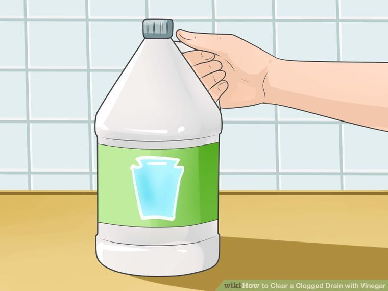 Try these tips and when in doubt, always consult with a professional plumbing service for help.
If you want to learn more about our services or schedule an appointment, contact us today.
Improving the efficiency of wastewater treatment plants | C.O.K. archive | 2012
At the first stages of treatment, wastewater enters with a high concentration of dissolved gases that are harmful to human health. In the methodology [1] in Appendix 2, the concentration of pollutants (PO) in evaporating saturated vapors is given. According to Appendix 2, we take the "Aerated sand trap" as the first step.
The following mass concentrations (measured in mg/m3) of gases in the wastewater entering it for treatment are given: hydrogen sulfide 0.0014; ammonia 0.014; ethyl mercaptan 0.0000013; methyl mercaptan 0.0000027; carbon 0.065; nitrogen dioxide 0.0038; methane 0.1. According to the method [1], the mass amounts of released pollutants are calculated when treatment baths are located in open areas and move above the water surface in air purification baths.
In the ventilation system considered in the article, the cleaning baths are located in the room, and the prepared atmospheric air is forcibly supplied by the fan of the supply unit. Therefore, the method adopted in [1] for calculating the evaporation of pollutants according to the air velocity that is possible in a limited low value does not correspond to the considered ventilation schemes. The fundamental difference is the removal of evaporated pollutants with exhaust air, the concentration of which is determined by the conditions of water evaporation processes and the concentration of gases dissolved in water.
Ventilation systems near baths with the release of water vapor and vapors of gases dissolved in water from the surface of the water are arranged according to the local ventilation scheme to trap the emitted hazards and the influx of outside air into the room in quantities that compensate for the amount of exhaust air.
The most complete removal of the formed secretions from the surface of water baths can be achieved by placing a receiving device above the water surface, which is traditionally made in the form of an umbrella according to the concept shown in Fig.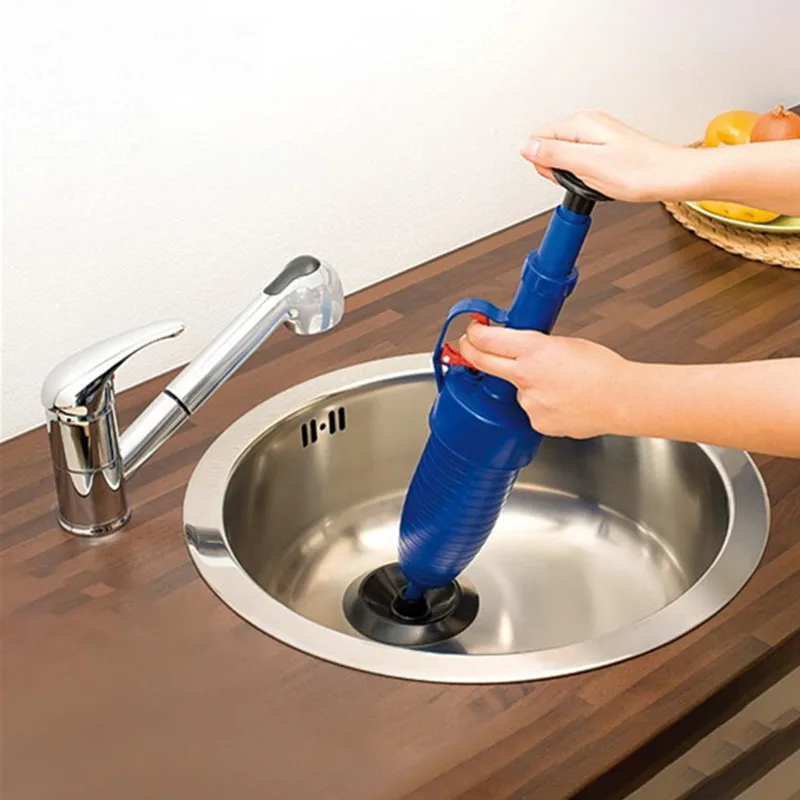 1 and taken from the recommendations [2].
Calculation of the ventilation system with the presence of umbrellas is carried out to determine the required exhaust air flow Lu [m3/h] for the perception of emitted harmful substances. In the recommendations for the design of ventilation systems [2] in Ch. 29 "local exhaust devices" the amount of air removed by local exhaust devices for cases where there are no sources of heat excess release is recommended to be determined by the expression (29.15):
where F is the inlet section of the umbrella, m2; V - air speed in the umbrella, taken from 0.8 to 1 m / s; Kt - the toxicity coefficient of harmful substances removed by the exhaust device, is taken according to Table. 26 [2].
In the absence of heat release, the dimensions of the cross section of the umbrella AxB must be greater than the dimensions of the source of harmful emissions by the value D = 0.Ne.
The equivalent diameter of the umbrella is calculated by the formula (29. 8) [m]:
Using this method, from the recommendations [2], we will calculate the operating mode of the exhaust hood over the “Aerated Sand Trap” bath with the size of the open section a = 15 m and b = 1.8 m. In the aeration mode, compressed air is supplied to the water column in the bath in the amount of 36 m3/h As a determining hazard, we take ammonia and according to Table. 26 [2] we find Km = 0.5. According to the formula (2) we calculate [m]:
With regard to the technological scheme of location in a room with a sequential overflow of purified water, it is extremely difficult to perform the increase in the dimensions of the umbrella section compared to the section of the bath with purified water recommended in [2]. As a rule, the size of the umbrella section is taken less than the size of the bath section.
:: Rice. 1. Traditional scheme of local ventilation using an exhaust hood (1 - exhaust hood; 2 - source of harmful emissions; 3 - zone of harmful emissions; VB - air velocity in the working area of the room, m/s; V3 - exhaust air entry speed into the hood , m / s; A-B - dimensions of the inlet section of the umbrella, m; a-b - dimensions of the section of the zone of harmful emissions, m)
From the analysis of the calculation formula (1) and recommendations to it [2], it can be concluded that the required exhaust air flow Lу does not depend on the intensity of the processes of evaporation of water and harmful gases from the surface of baths filled with water with gases dissolved in it. Therefore, in order to find the optimal energy consumption performance of ventilation systems for the premises of wastewater treatment plants, it is necessary to develop fundamentally new methods for calculating ventilation systems. In relation to the cleaning bath “Aerated sand trap”, the required exhaust air flow rate from the umbrella according to the formula (1) will be:
Lu \u003d 3600 x 48.1 x 1 x 0.5 \u003d 86580 m3 / h.
To create energy-saving ventilation systems for the premises of wastewater treatment plants, it is proposed to apply the energy-saving principle of displacement ventilation [3]. The determination of the required exhaust air flow Lу is made taking into account the intensity of the processes of formation of water vapor and gases during their evaporation from the water surface of the bath, which for the considered purification stage is Fvan = Fis = 15 x 1.8 = 27 m2.
In the textbook prof. P.N. Kamenev [4] provides an analysis of methods for calculating water evaporation modes and a generalized formula for calculating the amount of water evaporating from the free surface Wis [kg/h]:
where Fis - evaporation surface, m2; Pw is the saturation pressure of water vapor at the water temperature in the purification bath, mm Hg.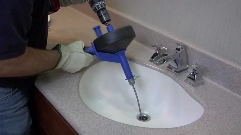 Art.; Pp - partial vapor pressure in the air entering the evaporation surface, mm Hg. Art.; Pbar is the measured barometric pressure of atmospheric air, mm Hg. Art. The evaporation coefficient Cis is numerically determined by the experimental formula:
Sis = 22.9 + 17.4 Vv (4)
[kg/(m2-h-mmHg)].
The air velocity Vv [m/s] at the water surface is determined by the conditions of supply of outside air. To implement the displacement ventilation scheme according to the energy-saving mode, it is necessary to ensure the supply of fresh air directly to the water surface, which is fundamentally different from the ventilation scheme according to Fig. 1.
In the ventilation scheme according to Fig. 1 outside air enters the room, and from the volume of the room - to the surface of the water in the bathroom.
Let us consider the conditions for the occurrence of evaporation processes in the warm period of the year when supply air enters the water surface.
In the climate of Moscow, the calculated air parameters are: tн = 26.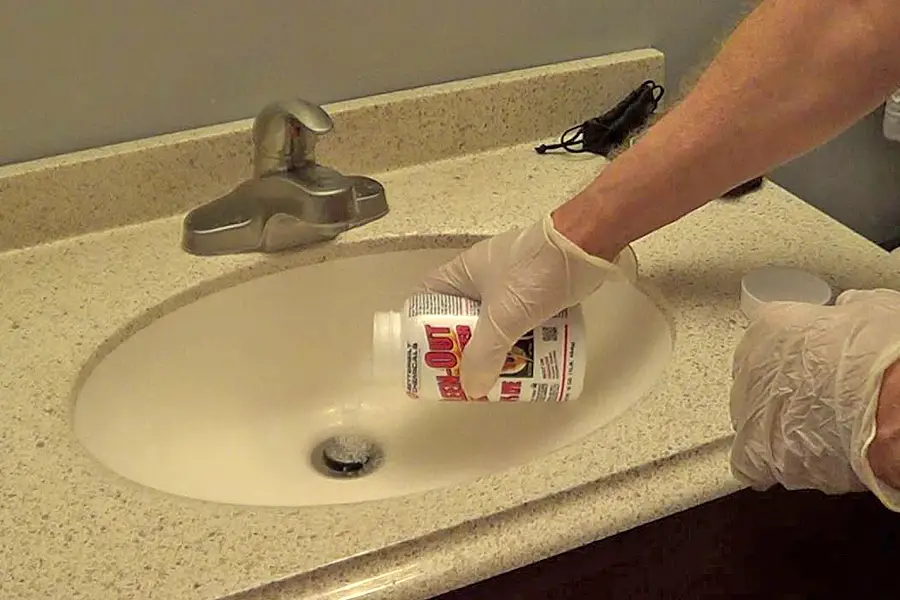 3 °C; dn = 12.1 g/kg; Rp = 14.1 mm Hg. Art. Estimated water parameters: tw = 25 °C; Pw = 23.8 mmHg Art.; atmospheric pressure Рbar = 745 mm Hg. Art. Air speed at the water surface: SW = 0.2 m/s. According to formula (4), the evaporation coefficient is numerically equal to:
Sis \u003d 22.9 + 17.4 x 0.2 \u003d 26.38 kg / (m2-h-mm Hg).
Outside supply air enters the water surface with Pp = 14.1 mm Hg. Art. According to formula (3), we calculate the amount of evaporated water from the surface Fis = 27 m2 in the cleaning bath “Aerated sand trap” in the mode of no compressed air supply for water aeration [kg/h]:
Moisture content of supply air dp = 12.1 g/kg. To find the moisture content of the exhaust air removed dу from the upper part of the umbrella, we apply the efficiency indicator for using the initial moisture content difference between the moisture content of saturated air dw = 20 g/kg at the water surface temperature tw = 25 °C and the moisture content of the outside air entering the water surface dp = 12. 1 g/kg. The proposed performance indicator is calculated by the formula:
Let's transform the expression (6) to find the moisture content of the removed air as follows:
To calculate dy by formula (7), it is necessary to have the values of the index Qd. Currently, there is no displacement ventilation scheme for wastewater treatment baths, and there is no experience of such studies. The work [3] presents data on the operation of displacement ventilation systems in swimming pools, and for them the indicator Qd = 0.5 was obtained.
According to our assessment, for the proposed displacement ventilation system for wastewater treatment baths, shown in fig. 2, the Qd will be greater than 0.5. This is explained by a more complete use of the initial mass transfer potential (dw - dH) in the scheme according to Fig. 2 compared with the pool ventilation schemes presented in [3].
Rice. 2. Scheme of ventilation of the wastewater treatment bath with displacement ventilation (1 -
supply and exhaust umbrella; 2 - bath for wastewater treatment; 3 - the surface of the treated water; 4 - exhaust duct; 5 - exhaust unit; 6 - sorption air filter; 7 - exhaust fan; 8 - supply air distributors; 9 - supply air ducts; 10 - supply unit; 11 - supply nozzle; 12 - guide inlet pipe)
Fundamentally new in the displacement ventilation scheme proposed by the authors according to Fig.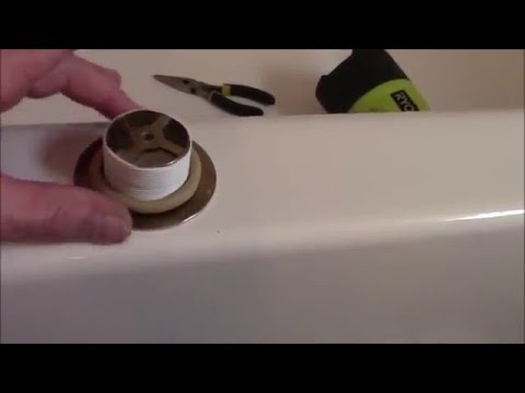 2 is the direction of the fresh air supply directly to the water surface through the supply nozzles 11 with guiding rotary shutters 12. The supply air Lpn to the bath 2 is supplied from the supply unit 10 and through the supply air ducts 9distributed over the air distributors 8, located around the perimeter of the bath. The umbrella has section dimensions AxB less than the size of the open section of the bathtub axb, equal to 27 m.
From the upper zone of the umbrella through the air duct 4 from the operation of the exhaust fan 7 in the exhaust unit 5, air contaminated with the treated wastewater is taken. To protect against atmospheric air pollution, the exhaust air Lu passes through the sorption material of the filter 6. This ensures that harmful gases are retained in the sorption material of the filter 6 before the exhaust air is released Lu into the atmosphere.
Let us take the value of Qd = 0.5, as established for the displacement ventilation scheme in the swimming pool room [3]. According to formula (4), we calculate the moisture content of the exhaust air removed from the upper part of the umbrella 1 (Fig. 2):
dy \u003d 12.1 + 0.5 x (20 - 12.1) \u003d 16.05 g / kg. Initial temperature difference between supply air and water:
(26.3 - 25.0) = 1.3°C.
The process of water evaporation requires an input of heat, and part of it will be taken from the cooling of the air during the evaporation process. Therefore, the process of absorption of evaporated vapors by air will proceed with a slight decrease in the temperature of the exhaust air, which we will take tu = 26 °C.
diagram of moist air of the design mode of operation of the supply and exhaust ventilation system of the wastewater treatment bath when organizing air exchange according to the displacement ventilation scheme according to fig. 2. To maintain the air balance, the amount of exhaust air removed Lу must be equal to Lpn.
According to formula (5), we calculate the required flow rate of fresh air into the area of the water evaporation surface in the cleaning bath to absorb evaporating water vapor [m / h]:
Application of the scheme of supply and exhaust ventilation of the wastewater treatment bath according to the scheme shown in fig. 2, compared with the traditional scheme of local ventilation according to the recommendations [2] according to the scheme in fig. 1 reduces the required extract air flow by 57 times (!):
Accordingly, the power consumption for the operation of fans in the supply and exhaust units will be significantly reduced. The cleaning bath “Aerated sand trap” periodically operates in the mode of supplying compressed air to the lower part of the water volume in the bath (water aeration mode). For the considered design of the cleaning bath, the compressed air consumption for aeration of the treated water is specified at 36 m3/h. The aeration mode has a significant impact on the modes of evaporation from the water surface of the bath. In studies by Finnish specialists [5] on swimming pool ventilation systems, a recommendation is made about a possible increase in the amount of evaporating water, calculated according to formula (3), depending on the modes of water use in the swimming pool bath.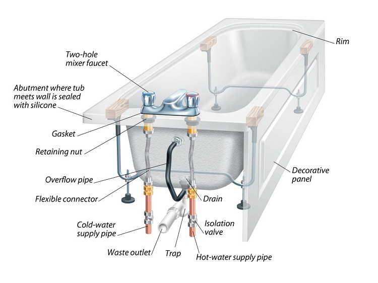
The following value of the coefficient of increase in the consumption of evaporating water is recommended: with calm water K = 1; during active health-improving swimming with full filling of the water bath by swimmers K = 2.
:: Rice. 3. Construction on the i-d-diagram of humid air of the design mode in the warm period of the year in the climate of Moscow according to the energy-saving scheme of operation of the supply and exhaust systems near the wastewater treatment bath (parameter change mode: N-U - absorption of water vapor and gases in the mode their evaporation from the water surface in the treatment bath; W-H is the initial potential of mass transfer between the parameters of saturated air near the surface of the treated water and the parameters of the fresh air).
The authors did not find in the literature descriptions, studies and recommendations for calculating the intensity of water evaporation from the water surface in aerated baths.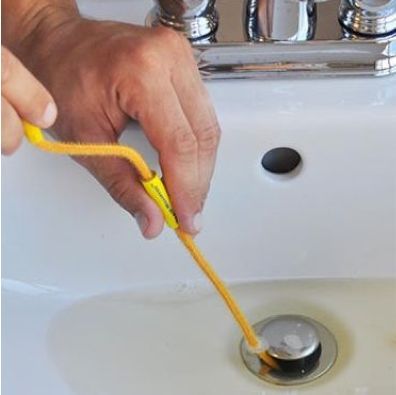 Field observations have shown that when compressed air is supplied at the bottom of the wastewater treatment bath, streams of air bubbles rise to the surface of the water. Air bubbles escaping through the water surface create numerous emission points, which resembles the water surface of boiling water. In the monograph of Academician M.A. Mikheev [6] described the regime of water boiling with the formation of steam bubbles rising from the volume of heated water. This mode of boiling is called "bubble boiling". Numerous studies of these regimes have shown a significant increase in heat transfer processes in bubble boiling regimes.
By analogy, the mode of water aeration with the formation of streams of air bubbles rising to the surface can be called "bubble modes of evaporation of water and gases dissolved in water." Authors of experimental studies of mass transfer processes in water aeration modes.
For a tentative assessment of the influence of the water aeration regime on the identification of evaporation processes, the amount of evaporating water, determined by the calculation by formula (3) at 7.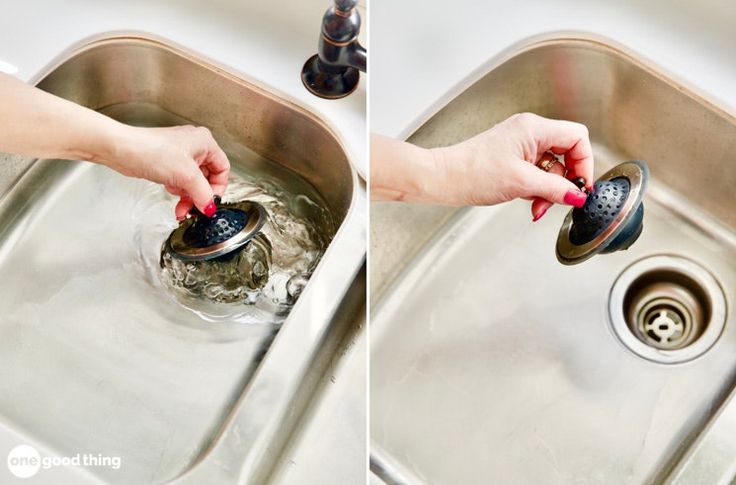 65 kg/h, is increased using the coefficient: K=2: Wis.aer+7.05x2.0=14 ,1kg/h
According to formula (5), we calculate the required flow rate of fresh air to compensate for the removed exhaust air:
To ensure energy-saving operating modes of the supply 10 and exhaust 5 units (Fig. 2), it is recommended to use drive motors for fans with two speed control. This will ensure the operation of the supply and exhaust systems with the minimum unavoidable energy consumption, as in aeration modes with a parameter value of
Lpn.aer = Lv.aer = 3061 m3/h, and in the aeration off mode at Lpn = Ly = 1513 m3/h.
_________________________________________________________________________________________________________________
Authors: O.Ya. KOKORIN, Doctor of Technical Sciences, Moscow State University of Civil Engineering;
V.V. VOLKOV, Deputy Head of the "VS" Department of JSC TsNIIEP Engineering Equipment
>>> Also read on the topic Wastewater treatment in SOK magazine 2010 No. 6
6
Calculation of the concentration of substances in washing and waste water in the galvanizing industry
November 8, 2016
The concentration of substances in wash and waste water is important for the organization of subsequent waste water treatment systems. Rinsing water is the water discharged from the washing baths after any one technological bath; wastewater is the total discharge of washing water from the washing baths after several technological baths, combined either by location (line, section, department, workshop), or by the type of substances they contain (chromium-containing, fluorine-containing, cyanide and other wastewater). The composition of wash water determines the type and parameters of local treatment systems, the composition of wastewater determines the type and parameters of general treatment facilities. Of particular importance is the value of the concentration of washed substances in non-flowing washing baths - it determines the frequency of water replacement.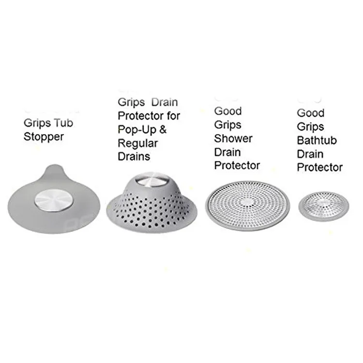
Recommended:
Cost of wastewater treatment plants for industry 9 examples
Calculation of concentrations for flow washing baths
If washing is carried out only in flow washing baths substances to be washed s to (g/l) is determined by the ratio of the rate of bringing the components of the solution from technological baths m (g/h) to wash water consumption Q (l/h):
(2)
(g/l) after a single and after cascading bathtubs of washing , the rate of delivery of it is proportional to the specific union of the solution from the previous technological bathtub m = Q F · C O · C O · C O O O O O O O O O O O O O O O O O O O O O OSA and the water consumption corresponds to the water consumption for washing after a specific technological bath according to the formula (3):
(9. 3)
3)
(g/l) after each co-current washing stage use the following formulas
after the first stage (4),
after the second stage (5)
and so on.
When determining the concentration of any substance in waste water, formula (2) is substituted with the total removal of this substance from all technological baths where this substance is present, and the total water consumption for washing for the corresponding section (workshop) or type of solutions ( acid-base, chromium-containing, cyanide, etc.):
Calculation of concentrations for still washing baths
The moment of the water change itself is determined by the achievement of the maximum permissible concentration of the washed component in the last non-flow washing bath in the direction of movement of the parts.
The change in the concentration of ingredients in the washing baths during the period of its operation between water changes (non-flowing mode of operation) is described by an exponential dependence that characterizes the non-stationary mode of operation of the bath. For stagnant baths (capture with periodic discharge), the concentration of substances in the washing water of the “n” washing bath is determined by the following formula:
(6)
in the non-flow rinsing bath, the concentration of the substance to be washed will reach the limit value, i.e. determine the duration of the stagnant flushing regime, after which a change of water is necessary. By found value τ according to formula 6, find the concentration of contaminants in the previous bath of non-flowing washing. However, for each specific case, it is not necessary to calculate according to such a complex formula. Instead, the following procedure is proposed for calculating the duration of the non-flow operation of the washing baths.
Figures 9 and 10 show the calculated values of contaminant concentrations in the stagnant washing baths and the duration of the stagnant operation of two and three rinsing baths, respectively, depending on the concentration of components in the process bath ( c o ) for the most common values of the limiting concentration of laundered components ( c n ).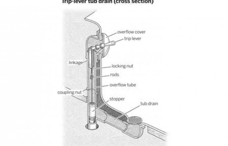
Table 9
The duration of the non -flowing mode of operation of the two bathtubs washing F = 1 m 2 /h, v pr = 1000 l, Q = 0.2 l /0.2 l /0.2 l /0.2 l /0.2 l /m 2
Table 100027 F = 1 m 2 /h, V pr = 1000 l, q = 0.2 l /m 2
9000
The volume of the washing baths is 1000 at 1000 l at a technological bath capacity of 1 m 2 /h and a specific removal of the solution of 0.2 l/m 2 .
Hourly water consumption for rinsing is calculated by dividing the total volume of the rinsing baths by the duration of the non-flowing regime.
If practical conditions ( s o , V ex . , F , q ) do not coincide with the above, in this case the table values are corrected for real conditions according to the following formula:
(9. 7)
7)
when washing in two trapping baths, the duration of the non-flowing period is from several days to several weeks, when rinsing in three trapping baths, from several weeks to several months, and when washing in four trapping baths, from several months to several quarters.
In addition, the duration of the stagnant regime increases with an increase in the volume and number of trapping baths and decreases with an increase in the specific electrolyte removal (with a complication of the profile of parts) and bath productivity. For example, when washing parts after bright nickel plating on hangers with a capacity of F \u003d 3 m 2 / h (specific electrolyte removal q \u003d 0.2 l / m 2 , concentration according to Ni 2+ s 9014 about \u003d 60 g / l or 270 g / l NiSO 4 7H 2 O) in two collection baths with a volume of 800 l (the maximum concentration of nickel in the last collection bath is s p = 0. 01 g /l) the duration of the non-flow regime is 24 hours (3 shifts), and in the case of washing in seven collection baths, the duration of the non-flow regime is 1493 hours, which corresponds to 180 shifts or more than 8 months of one-shift operation.
If the nickel plating capacity is reduced to 2 m 2 /h, then the duration of the non-flow operation of seven non-flow baths will be 2238 hours (273 shifts or more than a year of single-shift operation), i.e. in this case, only after a year ( ! ) of work, it will be necessary to replace seven washing baths with a total volume of 5.6 m 3 .
It should be noted that if the technological bath, after which washing is carried out only in non-flowing baths, operates with electrolyte heating, then the normalized water consumption in several non-flowing washing baths allows organizing a non-drainage operation by selecting such a number of non-flowing washing baths that would ensure equality of volumes water consumption and evaporation of liquid from the process bath.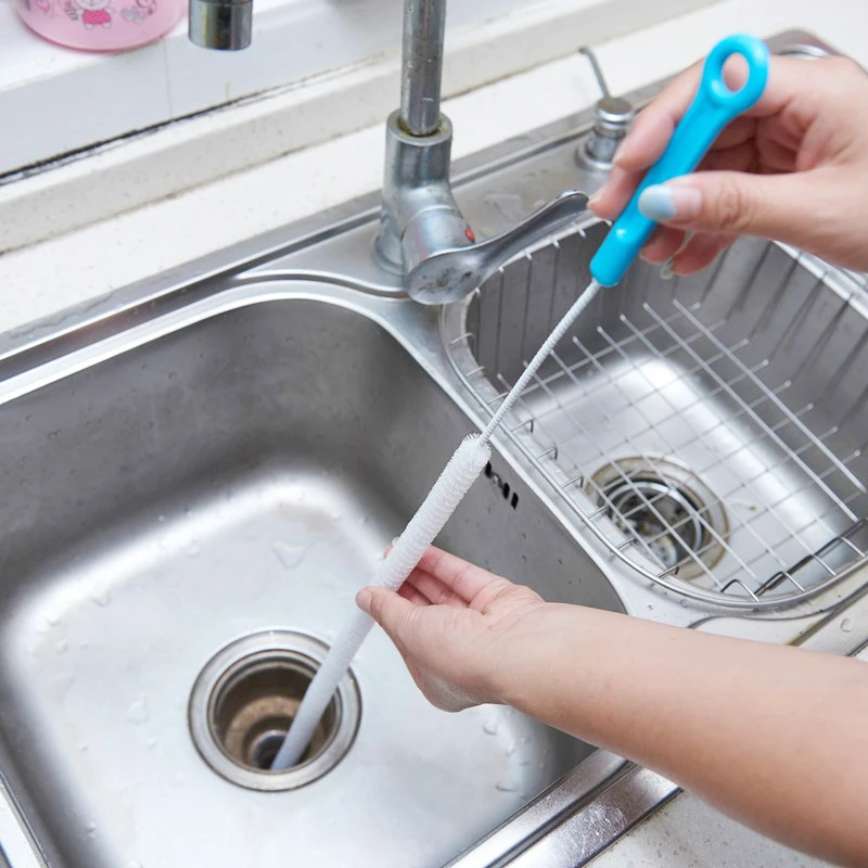 In this case, a complete return of the wash water to the process bath is ensured to make up for losses from electrolyte evaporation. For example, rinsing in four trap baths provides a drainless operation of nickel plating of parts on hangers at an electrolyte temperature of 50 °C and a capacity of 3 m 2 /h with the following parameters: specific electrolyte removal q = 0.2 l/m 2 , concentration according to Ni 2+ s o = 60 g/l or 270 g/l NiSO 4 7H 2 1 shows an example of the material balance of a drainless nickel plating operation. From fig. 9.6 it can be seen that after 353 hours (more than 2 months of one-shift operation), the wash water from the first trap bath is drained into a collection tank for acidification and subsequent adjustment of the electrolyte level in the technological bath, from the second trap pool water is poured into the first bath, from the third - into the second, etc.
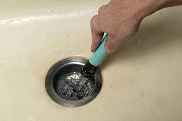 , distilled water or condensate is poured into the last trap.
Fig.1. Material balance of drainless nickel plating operation (nickel plating bath with internal dimensions 1500x1000x1000 mm and working volume 1300 l): volume of 800 l), operating in a periodically non-flowing mode, Sat - collection of wash water
where the same amount of water is added from the second trap bath, etc. In order to ensure drainless flushing under the conditions under consideration using only three trapping baths, it is necessary to heat the water in one trapping bath to 60 °C.
The presented scheme of drainless operation is not universal - the specific implementation of the scheme depends on the performance of the technological bath, the volume of the trapping baths, the area of the solution mirror, the concentration and temperature of the electrolyte, the complexity of the profile of the processed parts, the temperature and humidity of the ambient air, the efficiency of the onboard suction, holding time details above the technological bath, duration and intensity of washing.
Thus, we can draw the following conclusion about the appointment of baths with a periodically stagnant mode of operation (traps). Collection baths are designed for:
- capturing valuable and highly toxic components (precious metals, chromium (VI), nickel, copper, etc.) for their disposal or neutralization;
- make-up of baths with technological solutions operating at elevated temperatures, which simultaneously allows partial return of the components of the solutions to the technological bath;
- reduction of water consumption for washing by reducing the entrainment of process solution components into the washing water;
- organization of drainless operations;
- organizations of normalized water consumption, especially at low water consumption without the use of control and regulation equipment.
Calculation of concentrations during flow washing with one collection bath
substance carried away from the process bath m = q F s o , subtract the amount of material accumulating in the trap bath.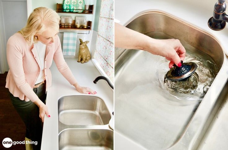 For an approximate calculation of the concentration of electrolyte components in the wash water with a stable operation of the trap bath, it can be assumed that 60% is retained in the trap bath, and 40% of the mass of the components removed from the process bath is carried away to subsequent flow-through baths (as in the case of calculating the water flow rate for rinsing in the presence of a trap bath). Then the formula will take a simplified form:
(8)
When the concentration of substances in the trap bath reaches half the concentration of the components of the process solution, the water from the trap must be replaced with fresh water.
The frequency of changing water in the trap bath is determined by the formula:
(9)
V – trap volume, l; q – specific entrainment of solutions, l/m 2 .
Collecting bath can be operated without changing the water in it . If you change the washing sequence, then you can not only not control the concentration of substances in the trap bath or the size of the area of the processed parts, but also eliminate the need for discharge and neutralization of waste water.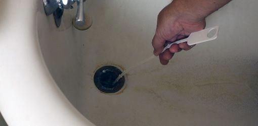
The proposed method consists in dipping the parts twice in the trap bath - the first time before processing (stroke 1 ), and the second time after processing in the technological bath (stroke 3 ) according to the scheme shown in fig. 2.
2. Changed scheme for using the trap bath: T - technological bath, Ul - trap bath, P - rinsing bath
which causes the concentration of components to be washed in the trap bath to tend exponentially to half the concentration of components in the process solution (Fig. 3. cr. 2 ). With the traditional sequence of parts movement (from left to right sequentially in baths T, Ul and P), the concentration of substances in the trapping bath exponentially tends to the concentration of components in the process solution (Fig. 3. kr. 1 ). Thus, compared to the flushing scheme without a trap, the entrainment of washed components into subsequent flow-through washing baths, the loss of chemicals and the cost of wastewater treatment, as well as the pollution of wastewater or the consumption of water for washing, are reduced by more than 2 times.