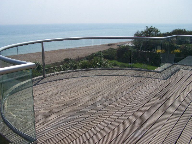
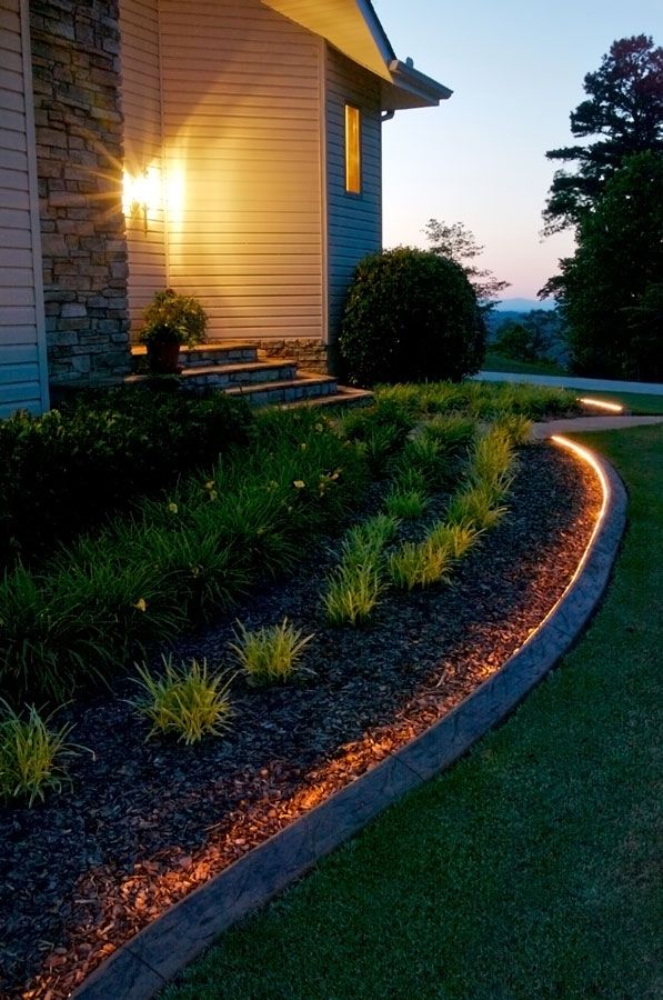
Curved deck edging
How to Install a Curved Deck Floor
By Brittney Smart | Published on
Buy Now
If you are building a deck, you might run into some architectural challenges. A right-angled deck is one thing, challenging enough to get right, but a curved deck adds quite a bit to the challenge. In this example, a redwood deck is being built up next to some existing curved concrete steps. This requires that the wood be curved to match. In this tutorial, we’ll show you step by step the most efficient and effective method we found for DIYing a curved wooden deck. We hope you find it useful as well.
Note: The author is an experienced, although not professional, builder. Use the advice set forth in this tutorial at your own risk. Always check building codes in your area before building. Neither the author nor Homedit is responsible for damages as a result of following this tutorial.
View in gallery
View in gallery
Before you begin installing your curved deck floor, you need to make sure you have your wall-mounted deck frame and deck floor joists in place first. Note: We recommend starting with the outer curved floor board first, before laying any other deck flooring, for a couple of reasons. First, you want enough space at the top of your curved board that you can mount it effectively, rather than having it taper off into a tiny point. Second, looks can be deceiving, and it can be hard to eyeball what is perpendicular when you’re looking at a curve. Aligning and laying this first curved board will improve the parallel nature of the entire deck floor.
View in gallery
To this end, run a precisely perpendicular chalk line from your house or the edge of your deck to the other edge of your deck. This chalk line should be perpendicular to your deck floor joists. As the starting off point of your entire deck floor, this line will be critical in keeping the redwood deck floor boards parallel.
View in gallery
Rip off several feet of wax paper. As in, the wax paper people use in baking. Align the edge of the wax paper with the chalk line (it should be out about 5” or 6” from the top of the curve) and tape into place so the wax paper runs straight.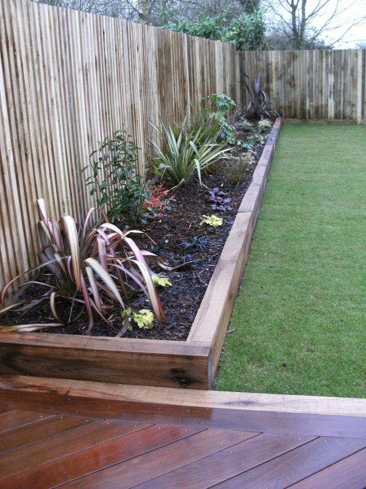
View in gallery
Keep the wax paper as flat and taut as possible, but don’t pull it tight. The taping won’t stick too well, and you’ll find yourself pulling the wax paper right off wherever it is you just taped it. But don’t worry; if you’re careful, this tape job will be good enough for our temporary purposes.
View in gallery
Use a dark permanent marker to lightly trace the edge of the curve. Keep the line precisely spaced along your concrete; so, if you start your line at the point of the concrete where it begins to curve down toward the ground, maintain that point all the way down your line. In this example, we drew the line about 1/4″ away from the concrete edge that we could see, but we maintained that same distance all the way down the curved line.
View in gallery
Carefully cut your wax paper along the line you just drew.
View in gallery
If necessary, and before you remove your wax paper, make sure the top of the paper is precisely aligned with the edge of your deck (in this case, the house wall).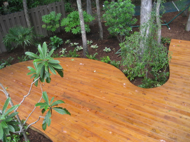 We had to tape a couple inches of wax paper onto the top to align it precisely. This is so you can align the wax paper onto your board exactly along the top end of your board.
View in gallery
Tape or carefully hold the wax paper onto your board, aligning the top and straight side. It’s important here to consider the amount of your board that you’re leaving intact. We recommend you leave at the very least 1” thickness of board all the way to the top; a little more is better, if you can. It’s a balancing act, though, because you also want to take care of as much of this very long curved edge as possible with one board.
View in gallery
Install a new blade into your jigsaw, or at least make sure yours is very sharp. While it may not be complete precision cutting, you don’t want the jigsaw to chew up your curved edge if you can help it. And a sharp blade will help you with this.
View in gallery
Use a jigsaw to carefully cut along your curve.
View in gallery
You may miss parts of the curve line initially; go back and get them again so that your curve is smooth and fits as precisely as you can manage.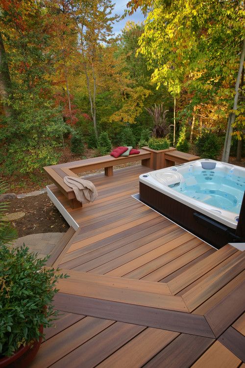
View in gallery
A jigsaw has a tendency to wobble a bit as you go. Just remember that if your curved line happens to have some bumps, your actual curved concrete step (or whatever) is likely very smooth. So, while you want to make sure you cut along the curved line, also be aware that the line’s small imperfections can be smoothed out with a smooth jigsaw cutting.
View in gallery
Dry fit the board to your curve. Make any adjustments needed. For example, if your gap between the board and the concrete is too great, consider cutting an inch or two off the top of your board to bring the whole thing in closer without sacrificing your curved cut. You can always sand out slightly wavy sections, if needed.
View in gallery
When the board fits perfectly in the curve, go ahead and lightly sand off the rough corner. Don’t get carried away here, though; you don’t want to change the curve.
View in gallery
Lay the board down, this time exactly where you want it. We recommend leaving a slight gap between concrete and wood for drainage purposes.
View in gallery
Remember your chalk line? Align the curved-cut board perfectly with the chalk line. Make sure the curve still works at all parts of concrete connection.
View in gallery
We’re going to be using Camo brand deck screws (2-3/8” for 2×6 redwood deck floor boards), because we’ll be using Camo deck spacers to install these curved pieces.
View in gallery
With the chalk line alignment precise, it’s time to install the curved edge of your redwood board.
View in gallery
With a helper holding the board firmly in place, predrill (we recommend a 7/16” bit) at a rather sharp downward angle the parts of the curved board that lie over joists.
View in gallery
Then install the Camo screws into the predrilled points.
View in gallery
Next, you’ll want to throw a couple of screws onto the concrete side of the board. Don’t get carried away here, though; you don’t need these every few inches. Predrill and screw into the point of the board that separates (curve-wise) from the concrete, into the wall-mounted deck frame. Then do the same at the top end of the board. Depending on the length of the curve, you might want to install another one in the middle of the curve (if it’s several feet long), but you don’t necessarily need to even do that, because the board at that point is so narrow, and you’ve already attached it to the joist on the flat side of the board.
View in gallery
With the curved part of your board installed, it’s time to turn our attention to the bottom (flat) portion of the board.
View in gallery
Work your way, joist by joist, down the length of your board toward the edge. Check for alignment with your chalk line EACH TIME you attach the board to a joist. As your first deck floor board, this one has to be perfectly parallel and aligned. It can’t be overstated, how important this is, to the outcome of your deck overall.
View in gallery
On each joist, attach your Camo deck spacer by pulling the lever, sliding the guides over the edges of your board until the spacer is flush with the board, and releasing the lever to clamp it in place. Then install the screws.
View in gallery
The beauty of this tool is that the screws go in at an angle, slightly below the top of your board, so it is a very secure attachment while being practically invisible at the same time. Win-win.
View in gallery
So, let’s take a closer look at the Camo deck spacer. Install it with the lever so it is directly over and parallel with the joist board.
View in gallery
Install the screw all the way down until the Camo drill bit stopper touches the deck spacer; in other words, until it can’t screw in any more.
View in gallery
Then, without moving the deck spacer, do the same thing through the screw hole on the other side of the deck spacer.
View in gallery
Remember that on the outer deck frame, where you doubled up your pressure treated lumber boards, you’ll want to attach the deck board to both framing boards, on both sides.
View in gallery
Moving inward and down along your curve, you’ll use this exact same wax paper/sharpie method for every board.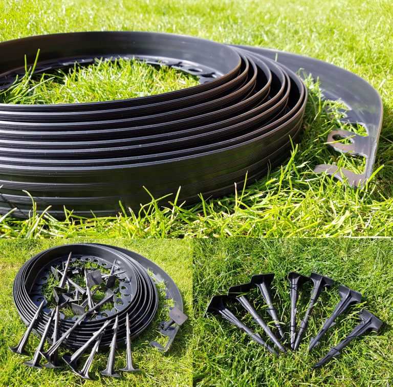 Be sure to mark, cut, and install each board individually before moving onto the next one.
View in gallery
When installing the subsequent boards along the curved concrete, we found this to be helpful: At the inner most possible joist, place the Camo deck spacer for spacing between the boards themselves. Then, pound in a wooden shim to maintain spacing between the concrete and your board while you predrill. Always be sure, when you are predrilling, that you’re doing so over a joist or a frame board. (Otherwise, what’s the point?)
View in gallery
Keeping the shim and deck spacer in place, predrill all the points you’ll need.
View in gallery
In this instance, due to the placement of the joists and frame, three holes were predrilled for the end of this particular curved board.
View in gallery
Install the screws with the deck spacer and shim in place for as long as possible. If you find you have to move the deck spacer in order to get a screw in, simply install the others first, then remove the deck spacer before installing the last screw.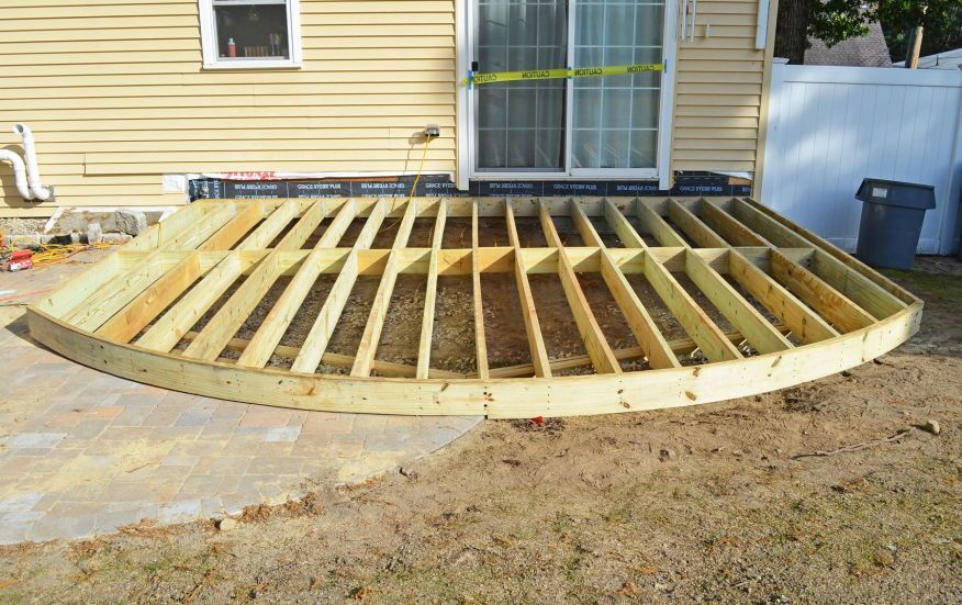
View in gallery
Remember as you are predrilling and installing screws that the angle of the Camo deck spacer screw holes is fairly sharp. Try to mimic this angle in your predrilling along the curve as best as you can, because that is what will give the screws the best security.
View in gallery
We recommend using two or three people to install each board – one on each side of the deck spacer to screw in the screws, and one to ensure the board is securely parallel and spaced evenly and precisely before screw installation even happens.
View in gallery
Leave the boards to overhang the frame at this point; we’ll cut them all evenly at the very end of your deck floor installation.
View in gallery
Piece by piece, you’ll get your curved deck installed. It looks beautiful when you’re done.
View in gallery
Even if it rains right after installation, you can still appreciate the beauty of a curved redwood deck, right? It’s not easy, and some curves are probably going to give you fits, but it’s absolutely worth it in the end.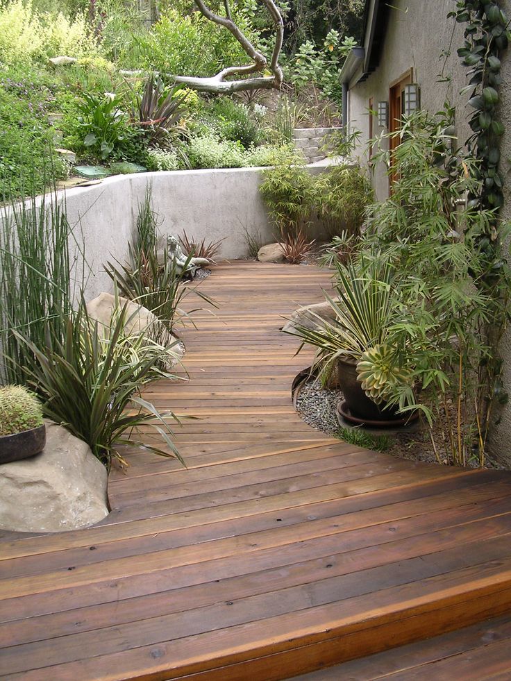
Step by Step Guide [with Pictures]
19548shares
- Share
- Pin
According to an old saying, every man must build a house, plant a tree and raise a son…. and build a deck 😉 I’ve planted a lot of trees, I have a son, I built a shed (it can count as a house), now it’s time to learn how to build a deck.
I didn’t just want any square or rectangular deck, I wanted something special. I’ve watched too much of the Decked Out television series on HGTV, so I wanted to build a beautiful curved deck. I wanted a challenge!
A deck is a place to enjoy the outdoors, an extra living and entertaining area. It enhances your house and lifestyle. A place to BBQ and watch the kids play in the yard. It’s a retreat you can build yourself. You don’t have to hire the professionals; you can plan, design and build it yourself. Are you up for the challenge?
Quick Navigation
- How to Build a Deck: Step by Step
- Step 1: Create Deck Design and Layout
- Step 2.
 Plan and Prepare the Site
 - Step 3. Building Deck Foundation
- Step 4: Install Deck Posts
- Step 5: Install Deck Beams
- How to Build Deck Beams
- Post to beam connection
- Angle beam assembly
- Step 6: Building Deck Frame
- The Ledger Board
- The Joists
- Step 7: Install Blocking Between the Joists
- Step 8: Install Deck Rail Posts
- Cedar vs Pressure Treated Pine
- The Posts
- Learning Curve
- Step 9: Laying the Cedar Deck Boards
- Bending Deck Boards
- Step 10: Install Deck Railings
- Step 11: Build the Deck Stairs
- Conclusion
How to Build a Deck: Step by Step
Step 1: Create Deck Design and Layout
STOP! Before you start buying materials and digging up the ground or tearing out what might already exist; sit down, take a breath and do some thought work.
Everything begins with design and planning.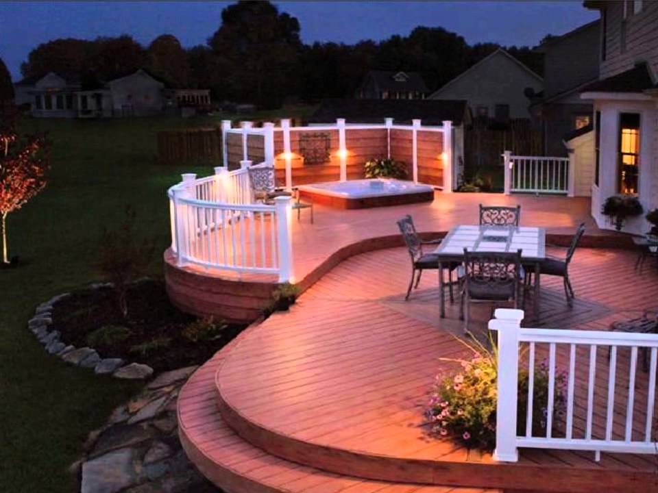 I’ve seen a lot of decks, even helped someone build one, now it’s my turn. What do I want to use it for? Do I want ground level or elevated, or even multi-level? Square, rectangular or curved? Do I want a hot tub or spa on it? And the kicker; what’s the budget?
Careful planning is the key to building a safe and enjoyable deck. If there are kids and a spouse or partner in your life, involve them; you don’t have to listen, but it does make life easier.
Gather your ideas up, and then begin to sketch out your plan. The more thought you do before you pick up the hammer and saw, the less work you make for yourself.
Here’s my plan:
- One-level deck
- Connected to the house – ledger board is already installed
- On the right side (looking out from the house) place for BBQ
- Planning to add custom pergola so 2 post rails will be 8 feet high
- Curve the left part of the deck as sitting area
- Diagonal decking (changed later to parallel)
- Decorative rhombus insert in the center
The plan makes the design.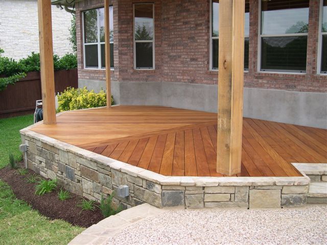 I know what I want; now I have the fun of figuring out how to build it.
As usual the fun begins by checking with the local Building Department and Homeowner’s Association about building requirements and permits. The Building Department usually is very helpful and provides information about footings, beams, guardrails, and stairs.
The building department should also identify if there are concerns regarding wind load, seismic issues, snow loads and soil conditions which may be unique to your location. They probably won’t say anything about lateral force support though.
If you’re planning on large gatherings on your deck or have kids who run, stop, jump and dance around, you may want to add diagonal bracing between beams and posts to control lateral movement.
You should also check for any underground utility lines (water, gas, power, communication, etc.). It’s a free call in North America to: One Call Referral Service (1-888-258-0808).
They’ll usually send someone to identify and mark out any concerns. It’s better to find out before you start if something is buried where you want to build your deck, then you can adjust the design if need be, or move your location.
Here’s my setup:
Footings
- Concrete pilings at least 4’ deep due to frost issues
- 12” in diameter to support more weight
- Galvanized post base set into center of concrete piling
Support Posts
- 6×6 pressure treated post will carry more than 4×4 posts and won’t require different size for tributary posts (posts that support middle of the beams and carry 2x the end post load)
Ledger Board
- Mine was pre-installed by builder with flashing and metal wrap. It was mounted to the house rim joist approximately 4 3/4” below the bottom of the patio door to give protection from snow build-up, and easy access from the house.
Beams
- 2 triple 2×10 main beams parallel to the house
The first located 3’ from the house and supported by 2 posts
The second locate 12’ – 6” from the house and supported by 3 posts - 2 double 2×10 beams angled between parallel beams and supported by 1 post where they meet
Joists
- 2×10 pressure treated joists at 12” centers – the thickness of the plank is a rough indicator of what it can span in feet without support; 10” spans roughly 10 ft.

- Attached at ledger board with metal joist hangers
- Attach to beams with hurricane hangers or joist-to-beam straps
Joist Span
- 13’-6” joist supported by 2 beams at 3’ and 12’-6”’ from the ledger board
Decking
- 5/4×6 cedar decking
Railing
- The deck will be about 4’ from the ground so railings are a requirement
- 4×4 cedar posts anchored to the deck with blocking and bolts
- Guard rails will be 38 inches high – the Building Department will tell you the minimums
- Balusters will be installed so a 4-in. object can not pass between them.
Stairs
- Pressure treated stringers on two 8” diameter concrete footings
- Attached to the deck frame with metal brackets
With all these parameters I created deck design using Realtime Landscaping Architect
Required Tools (Available on Amazon):
- Tape Measure
- Mason Line
- 48-Inch Level
- Safety Glasses
- No products found.
- Deck Boards Straightening Tool
- CAMO Marksman Pro-NB Tool
- Laser Level
- Drill and Impact Driver Combo Kit
- Circular Saw or Miter Saw
- Nail Gun
Step 2. Plan and Prepare the Site
Once you have the required permits and are ready to begin, it’s time to clear the building site. Construct four or 6 Batter Board frames and hammer them into location.
Use mason string or twine to outline and square the plan. The marking paint makes everything visible and marks the location of important building references. Make sure you triple check the location of all footings; they don’t move easily and they need to be centered under your posts.
Batter Boards
- Batter boards are H shaped frames installed outside the corners of your build site. They are used with a mason string to outline and square your layout. A stake hammered tight to the house will serve the same purpose, but use batter boards for corners away from the house
- Level the string as much as possible, and square it – the square root of sum of the length squared and the width squared should be the length of the diagonal between the start of one and the end of the other
- Remember to mark the final string location on the batter boards so it’s easier to reattach should the string be moved or broken
Site Preparation
- Remove any obstacles within the outlined area, and several feet outside it to.
 Then remove the sod and top layer of soil
Marking paint
- A spray that can mark vertically and used to outline the build site
- Mark the post hole locations with an X and drive a stake to mark the center of the post hole location
Stakes
- A pointed 1”x2” length of wood used to mark corners, post hole centers, and other important building references.
Mason line
- A no stretch string or twine used by masons and builders to identify level or straight line distances between reference points.
Footing locations
- The string outlines and parallels your deck edge. Measure in from the string and out from the house to identify where each footing pier/post hole will be located
- Make sure to double and triple check your measurements, you want the support posts centered on the footing and aligned with the beam it will carry
Stairs location
- Mark in the stair location to align supports and footings/postholes.
 For my deck I’ll need two 8” footing/post holes to support the bottom of the stringer.
Batter boards and mason string used to square the layout. Marking paint outlines the layout. The stakes are building references for footings/post holes.
Step 3. Building Deck Foundation
After making sure the marking paint and stakes were in the correct location, I was ready to dig the 6 holes. The deck will be attached to the house so the footings have to go below the frost line which is 4 ft. deep in my area.
I’m using 12” x 8 ft. sonotubes to line the holes. The 12” diameter provides a wider base to support more weight, and the tubes are easy to cut with a handsaw.
A little mental math: 6 holes X 4 ft. X 1 ft. (12”) = 24 cubic feet of digging. No problem. I began digging one of the 2 holes closest to the house.
It was hard packed sandy soil which had been partially backfilled and packed. The first 2 feet went fairly well, but the deeper I went the less power I had.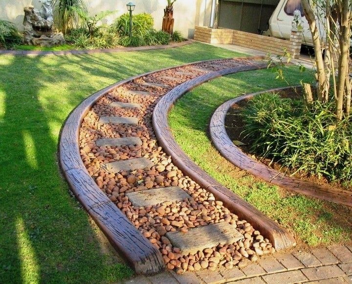
I was successful! One down and five to go; four of which were in fully undisturbed soil.
I went down to my local equipment rental company and rented a Motorised Hydraulic Auger with a 4’ auger and extension, and a manual post hole digger. The Motorised Hydraulic Auger is a cantilevered affair so most of the torque goes into the machine and not the operator.
I practiced on my hand dug hole; tidying it up and widening it at the bottom and going a couple inches deeper.
The 5 holes went much easier. My soil is sandy loam clay with small rocks so the auger worked well. Make sure the holes are vertical to prevent frost from lifting against the concrete pier.
If your soil is rocky you may want a helper or two. The auger will still do the job, but needs more weight at the auger end to continue to drill downward. If you have bed rock closer than the frost line, then bedrock is how deep you go.
With the holes dug, I removed any loose dirt, and then packed down the bottom as best I could. I used the head of a sledge hammer reaching down the hole and tamping the bottom; more effective than a garden hoe.
You want the bottom to be flat so the weight of the deck pushes on a flat surface. To provide some drainage I also tamped gravel into the bottom the holes; making sure I still had a depth of 4 ft.
The sonotubes went into the holes next. They’re easy to cut, light to handle, keep the concrete where you want it, and the smooth sides resist lifting by frost.
To make a straight cut on a round tube isn’t easy; I used the newspaper method (see Pro Tip). Make sure you level the top of the sonotube and that it is at least 4”s above the grade to keep wooden posts dry.
I used 1”x2” laid across the sides of the hole and screwed to the outside of the tube to keep them from shifting. Wooden wedges between the tube and the hole will work too.
Pro Tip: To cut sonotubes make a template – tape together two or three pages of newspaper, wrap the sheet around sonotube. Keep the sheet snug. Tape the end of the sheet to itself. To mark the cut line just slide the sheet to the cut point.
Before filling the tubes with concrete, I cut 3 ft. lengths of ½” rebar. The plan is to push two pieces into each hole after they’re filled with concrete.
The rebar provides additional strength to the concrete and a better foundation for your deck. I used an angle grinder to cut the rebar, it was easier. I also prepared my favorite 6×6 adjustable deck supports so they were ready to insert into the concrete.
With everything ready, it was concrete time! I knew the 6 holes would take approximately 24 cubic feet of concrete, plus 2 extra for the part above ground level.
A cubic yard is 27 cubic feet (a cubic meter is 35.3 cubic feet), so having concrete delivered was going to be too expensive; there’s often a surcharge on small loads too. Bags of ready to mix it would be.
A bag usually does ½ a cubic foot, so I’d need approximately 52 bags. I chose the high strength which cures to 4000 psi in a month. The minimum for a footing is 2500 psi, but 4000 psi is recommended.
The instructions for mixing concrete are on the bag. You don’t want it too soupy or wet as it reduces the compression strength. If it’s too dry it can create fracture lines and air pockets which over time cause the concrete to crumble. It needs to be wet enough to slowly slump, but dry enough to stay mounded in the shovel.
I decided to rent a portable gas powered mixer ($50 for day) from my local equipment rental company. I could have mixed the concrete by shovel or with Lightning Pro concrete mixer in a wheelbarrow, 2 or 3 bags at a time, but it would take longer.
Each footing would require a bit more than 8 bags, by mixing 4 at a time I could fill half a sonotube in two wheelbarrow moves. Don’t mix and move more than you’re comfortable handling.
I began with the two closest to the house and then the single one. After filling half a sonotube, I pushed the shovel up and down in the tube a couple of times to remove air pockets.
Once I had the tube full, I again used the shovel to remove any air pockets in the upper half, and then inserted the two rebar lengths.
After filling the first 3, I reset the mason line on the two closest to the house and inserted my favorite adjustable deck supports aligned with the string and centered in the tube.
I did the same process with the last three footings. I then cleaned everything up with the garden hose so the tools were as clean as before I started.
To help slow the surface drying time and prevent flaking or cracking, I covered each tube with damp fabric. I kept them damp for about 24 hours. The forecast was good so I didn’t have to cover with plastic, but was prepared if the weatherman was wrong.
After everything had dried, I removed the batter boards and cleaned up the site. I made sure the ground sloped away from the house; I didn’t want water backing into the basement.
I filled in around the sonotubes with dirt and covered with gravel.
I rolled out landscape fabric over the whole are the deck would cover, and spread a 2 – 3 inch layer of gravel over it.
My foundation for the deck was done.
Step 4: Install Deck Posts
The posts to support my deck are pressure treated 6” x 6”, and provide a much stronger base than 4” x 4” material. The difference between buying 12’ and 8’ long material and cutting it for my deck posts is a saving of pennies a linear foot, so get what works for you. To determine my material requirements I needed a more accurate measurement.
I attached a joist hanger to each end of the ledger plate, measuring to ensure they were positioned properly. I then rested a 12’ plank in them, held the other end up until level, and measured down from the top of the plank to the base of the adjustable post bracket. This gave me a usable measurement to work with.
I knew the deck surface would be 4 ft. above the ground at the house due to the ledger board, and my measurement at the footing was 49”.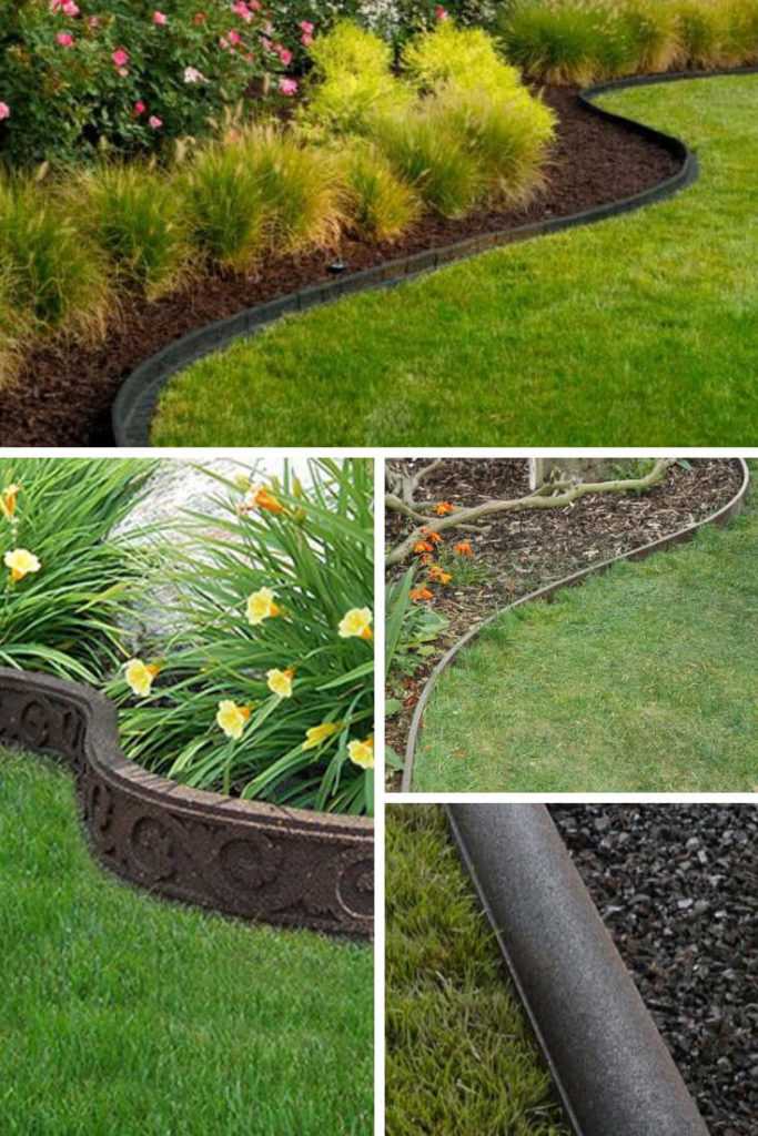 I added an inch to the 49” for the deck board for 50”.
To determine the length I would need for my posts I did a little math. 1” deck board (5/4”) + 9 ½” (10” joist) + 9 ½” (10” beam) = 20” of structural material sitting on the post, so 50” – 20” = 30”. The adjustable post brackets allow for any final adjustment. I would need two 8 foot 6” x 6” posts to get my 6 posts.
Pressure treated material is often high in moisture content due to being immersed in a chemical bath. As wet lumber dries, it can twist, split, or check. Posts are often cut from the middle of a log so there are a number of things to look for when selecting posts.
After checking along the length of the post for curves and twists, look at the end grain. If the core or pith is in the middle at both ends, or close to the middle, it will dry straighter.
If there is no pith, look for grain (tree growth rings) that is close to parallel with one face of the post, it too will dry straighter.
I treated all cuts with a copper naphthenate–based preservative to protect the fresh wood, and to comply with the building code. I assembled the adjustable 6×6 deck supports and attached the posts to them using 2 ½” Simpson Strong-Drive Structural screws.
Using a post level and braces, I leveled and secured the posts into position. I was now ready to build the beams.
Step 5: Install Deck Beams
How to Build Deck Beams
I needed to build two 3 ply 2×10 main beams 13’–2” long, and two smaller 2 ply 2×10 angle beams 70” long. Pressure treated dimension lumber usually comes in 12’ and 16’ lengths, but seldom 14’.
When selecting dimension lumber for beams always look for straight planks; a curve or twist is difficult to straighten. If the plank has a slight crown, it is acceptable.
Cut the planks to length, ensure all crowns are up, and nail or screw the planks together every 12” – 16” inches; some local codes also require carriage bolts to be used every 2’.
I also cut the exposed end of the beam at a 45 degree angle; aesthetically it looks better but allows water to drip off the beam easier. Remember to treat all cuts with a copper copper naphthenate–based preservative.
I used self-adhesive bitumen membrane and tar paper on top of posts to prevent water rotting the posts, and covered the top of the beams with the membrane to protect it from moisture.
Post to beam connection
I covered the top of each post with self-adhesive bitumen membrane and tar paper to prevent water entering and rotting the posts. The membrane or tar paper also prevents the copper in the wood preservative from eating the zinc in the galvanized metal brackets. The new pressure treatment may be more environmentally friendly, but it eats the zinc up like a kid eats candy.
Where the beam would sit on the galvanized brackets I also covered with the self-adhesive bitumen membrane.
For beam to post connections I used Simpson ZMAX brackets and 2 ½” Simpson Strong-Drive structural screws. The ZMAX is supposed to better resist outdoor and pressure treated corrosion.
How the beam is connected to the post is extremely important. The weight of the deck sits on the beams which transfers the force directly to the posts for support.
The connection has to keep the beam connected to the post, resist post and beam twisting, and prevent wind uplifts. The method I used places the beam centered fully on the post making for the greatest support.
Using correctly sized post to beam brackets helps prevent twisting of the beam and rotation of the post. I also used the stronger hurricane brackets to connect the joists to the beam, which also prevent twisting at the upper edge of the beam, and wind lift.
I also installed diagonal bracing between the posts and the beam. This creates lateral support and also helps prevent twisting. All decks that sit two or more feet above the ground should have lateral bracing.
Some Other Options:
The notched post to beam connection has the post notched half way across at the top making a chair for the beam to sit upon. Carriage bolts are used to connect the beam to the post.
The thickness of the beam determines the thickness of the post since it is better to have the beam fully supported on the post. A 2 ply beam is 3” thick and a 6X6 is 5 ½” thick, so notching out a rest for the beam leaves 2 ½” of the 6X6 for bolting the two together.
A 3 ply beam is 4 ½” thick which would leave no more than an inch for the connection, which isn’t enough; so a larger post would be needed. If a 3 ply beam is only partially seated on the notch, then the downward force isn’t fully carried by the post.
This can reduce the ability of the beam to carry the weight and cause a diagonal force against your post, causing it to fail. It is great for preventing the beam from twisting, but if the post rotates it can split under the notch.
On smaller decks a post sandwiched between two single planks bolted together at the posts is an option. It is great for preventing the beam from twisting and the post from rotating.
Remember to block between the planks that form the beam to prevent it from twisting. Also, the weight transfer for the connection creates a sheer force as it is carried by the bolts holding the planks to the posts.
The real problem is corrosion of the bolts by the copper in the pressure treatment causing the connection to fail.
Angle beam assembly
Assemble the two shorter 2 ply beams the same way as the large beams. I found it easier to mark the ends for angle cuts by resting them on the posts.
Treat the cuts and cover all connection points with the membrane before attaching the galvanized connectors. I used Simpson Strong-Tie ZMAX 18-Gauge Galvanized Framing Angles plus straps to secure the beams to the posts.
Adjustable deck supports allow for easier beam leveling.
Step 6: Building Deck Frame
The Ledger Board
The 2×10 or 2×12 ledger board attaches to the house at the rim plate, or to the concrete or brick foundation wall.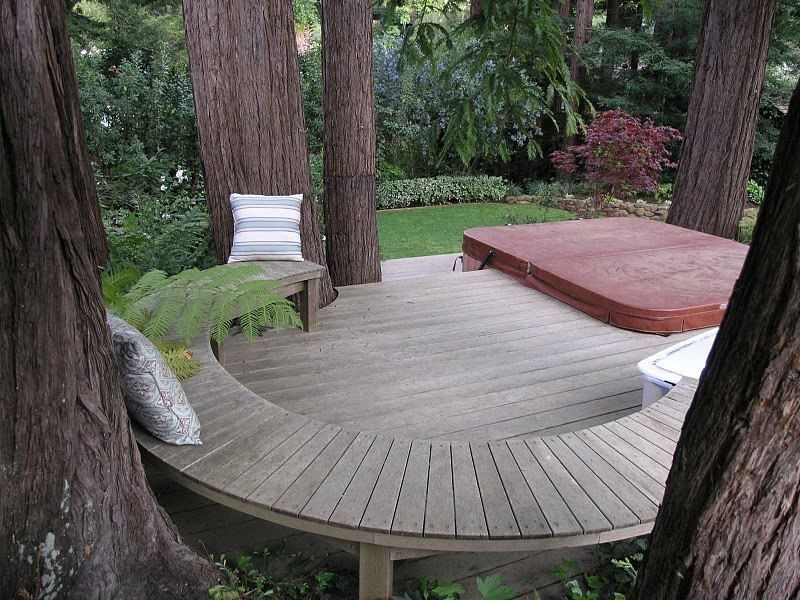 Never attach a ledger board to brick veneer; it is usually only attached to the house with metal brick straps.
The ledger board is attached to a concrete or brick foundation using ½” concrete anchor screws. Predrill ½” holes in the ledger board, position it against the wall using temporary supports and ensure it is level.
Use a concrete bit and drill your holes every 18” to 24”. Bolt the ledger to the wall, attach and seal flashing above.
To attach a ledger to a house with siding requires a bit more work. Before removing any siding, make sure there is enough space below access doors to permit attaching the ledger to the rim plate and sliding at least 4” (8” is better) of flashing up under the siding.
Mark the siding to be cut and removed. Use a sharp utility knife and straightedge to make the cuts, trying not to cut the house wrap. Slide a flat pry bar up underneath to pop out the nails holding the cut siding and remove.
Install a 14” – 16” strip of galvanized metal where the ledger will attach.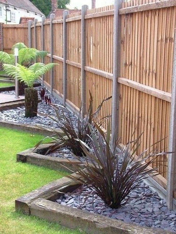 The bottom 2” should stick out below the ledger and be bent at a 45 degree angle as a drip edge.
Make sure the metal goes 8” behind the siding at the ends of the ledger. Caulk the upper edge, then cover with self-adhesive bitumen membrane to avoid water penetration into the ledger board as it provides self-sealing around nails and screws.
It also separates the metal from the pressure treated wood. Attach the ledger board using ½” lag screws. The last piece of galvanized material slides 4” – 8” up under the siding; it may need to be notched for the door and siding nails. The bottom 2” – 3” needs to be bent to sit flat on the ledger.
Pro Tip: Measure and mark the ledger board to identify where the joists will go before attaching it to the wall. That way the bolts attaching the ledger to the wall won’t be in the way when attaching the joists.
The Joists
The floor joists are the main support for the deck boards and give the deck its shape. The joists rest on the beams and connect to the house at the ledger board.
My ledger was pre-installed by the builder, so it was metal wrapped and flashed prior to the house siding going on.
I used 2×8 joist hangers to attach the joists to the ledger board. I spaced them every 12” which creates a more solid support than every 16”.
The 2×10 pressure treated planks were cut 13’-1” long. Wherever wood and metal would connect, I used self-adhesive bitumen membrane to avoid water penetration into ledger board as it provides self-sealing around nails and screws, and separates the corrosive zinc and copper combination.
I placed the joists in the hangers, resting them on the two beams. 2 ½” Simpson Strong-Drive Structural screws were used to connect the joists to the hangers. I measured the joist spacing on the beams, and used hurricane brackets to connect the joists to the beams.
I used tar paper to separate the joists from the brackets, and sealed all cut ends with copper naphthenate–based preservative.
Attach the joists to the ledger board with hangers and structural screws.
Attach the rim joists using concealed face mount joist hangers.
I connected the joists to the beams with Simpson hurricane brackets.
I did a final deck leveling check and made sure that there was a slight slope toward stairs.
Step 7: Install Blocking Between the Joists
Joist blocking, or bridging, should occur every eight feet, or less. It reduces joist wobble and bounce, and helps prevent the joists twisting. The blocking should be attached flushed with the top of the joists.
I used the end scraps from my joists to reduce waste. I treated all cuts with copper naphthenate–based preservative to prevent rot.
Use a string line and snap a line perpendicular to the joists half way between the beams. Attach the blocking in an alternating pattern on either side of the string line mark to make nailing easier.
The spacing between joists should be the same, so you should be able to cut the blocks the same length. Rim joists however may be spaced differently and need blocks of a different length.
I also used blocking around the perimeter, or rim, of the deck to stiffen the outside joists and provide attachment points for the railing posts. A 3 point attachment makes a stronger and more stable railing than a 1 or 2 point attachment.
I did a lot of cutting (kudos to my No products found.) to make all the blocks and used pounds of screws to attach them in place. The stable deck frame made it worth the extra effort.
Curve framing
I spent a lot of time laying out the joists for the curved deck. I tried to keep the maximum distance between joist ends 12” at center.
To provide the maximum support I narrowed the distance by angling the short joists and attached them to the rim joist using metal angle brackets. That was the tricky part as some short joists were cut with an angle. I did a lot of blocking between the rim and neighbor joist to stiffen up the rim joist.
I found the center of the circle and attached a 1×4 board to the framing with a screw to mark the center. The drawing of the circle was really easy then.
To draw the circle I attached a string to the screw with a pencil at the end, and marked the circle on the joists. I used tape to make the circle more visible.
I cut the joists with a 7 ¼ circular saw. Some joists were cut at an angle. I then added more blocking to frame the outside of the circle and provide attachments for railing posts.
Step 8: Install Deck Rail Posts
Cedar vs Pressure Treated Pine
The structural framing of the deck was made with pressure treated pine. I chose to use cedar for the posts and decking for several reasons.
Cedar will not twist when exposed to moisture and it has no corrosive chemicals to leach out. It handles temperature changes better than pressure treated material, and requires less maintenance to keep clean.
It is softer than pine, so don’t use a pressure washer to clean it; it will gouge it.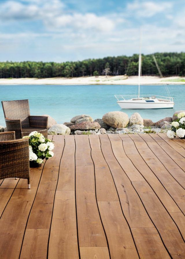 Cedar is also resistant to rot so it doesn’t need chemical preservatives unless it touches the ground. If you decide to stain it, you’ll have to stain it every other year or so to maintain the color.
The major drawback to cedar is the cost; it is expensive. By building the support system for the deck with pressure treated pine I saved a lot.
The Posts
I used 4×4 cedar posts for the railing supports. Attaching them to the joists and rim joists with blocking and ½” hot dipped galvanized carriage bolts with washers and nuts.
I used two bolts and drilled the holes offset diagonally to provide more stability. Once all posts were bolted in place, I made sure the nuts were tight, and then covered the exposed ends with silicone to prevent rust.
All the railing posts were the same length, but final trimming was done after the decking was installed. The two 10’ long 4×4 posts that would support the pergola over the BBQ were extended below the joists and flush with the bottom of the beams.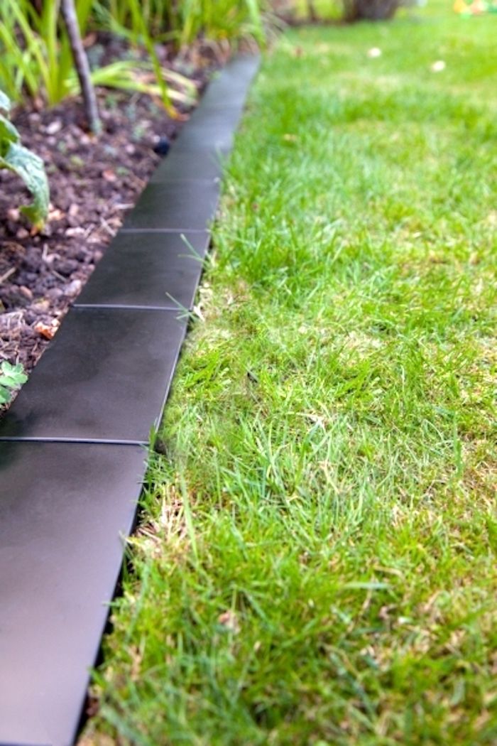 I screwed them to the beams for extra support and stability.
With the railing posts installed, I removed the temporary bracing. I angle cut and installed 4×4 diagonal braces between the outer beam and the support posts to prevent lateral movement.
After making sure the bolts were tight, I used silicone sealant to cover bolts and nuts.
The holes were drilled diagonally for better post stability.
The 10’ long posts were also attached to beams with structural screws for more stability.
Learning Curve
I initially installed the blocking for the center divider decking boards and rhombus horizontally. It rained before I could install the deck boards and I realized the horizontal blocks had cupped due to the moisture and heat and were holding water. I removed the blocks and reinstalled them vertically.
I used pressure treated 2×4 horizontally for the blocking between the angled joists of the curved deck.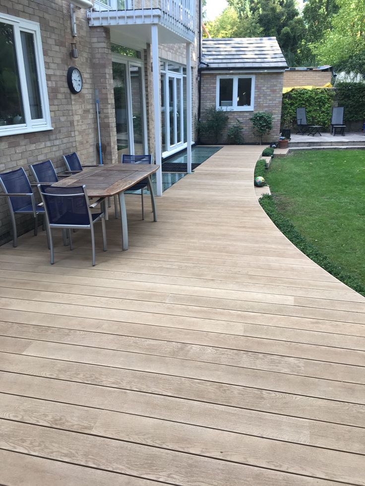 They provide support for the deck boards and backing for screws.
Step 9: Laying the Cedar Deck Boards
In preparation for installing the 5/4”X6” cedar deck boards, I coated the top of the joists with preservative. I then covered the top of the joists with 3” strips cut from rolls of tar paper. I could have used Shadoe Track or joist caps, but the tar paper does as good a job and costs a lot less.
To attach the deck boards I used a Marksman Pro Tool and CAMO screws. The CAMO system uses hidden side fasteners so there are no screws in the top of the deck. It also automatically keeps the space between deck boards. It worked really well.
In a perfect world all deck boards would be straight. To help straighten some of the deck boards I used a deck board straightener tool.
No screws are visible thanks to the CAMO system and the hidden side fasteners.
Bending Deck Boards
The most challenging part of the deck was bending the trim boards for the face of the curved deck.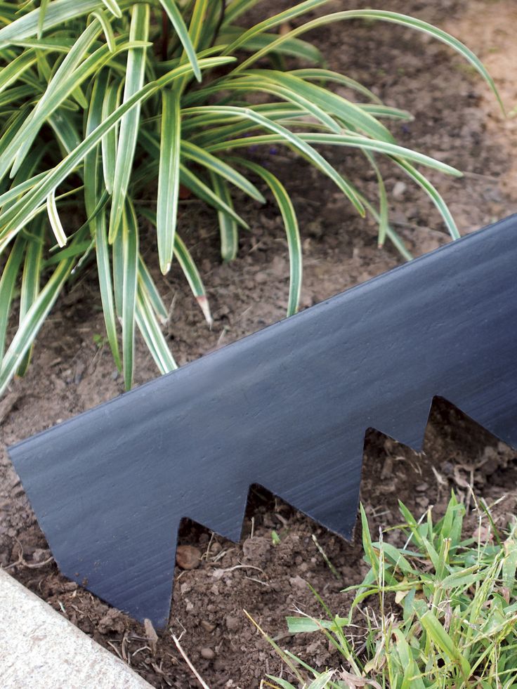 I used the Kerf bending technique to bend the boards.
Kerfing meant making cuts 1” apart and 2/3 of the way through the board; this removes enough wood material to permit the board to be bent without cracking or breaking.
I had 2 boards 10′ = 120” – 2 = 118 * 2 = 236 cuts and 2 boards 104” – 2 = 102 * 2 = 102 cuts; that’s 338 cuts! It’s a lot of cross cuts with 7 1/4 circular saw. Take your time; you want all the cuts to be perpendicular so the boards bend.
The cuts are 2/3 of the way through the 5/4 decking board, so they’re 24/32” deep. It takes the rigidity out of the board and allows it to bend around a curve.
I attached one end of the board to the deck framing while my wife was holding the board in the middle, I then slowly bent it and screwed it to each joist.
Step 10: Install Deck Railings
As I finished installing the deck boards my focus turned to the railings. The local codes dictate the minimum height the railing can be and the spacing between balusters.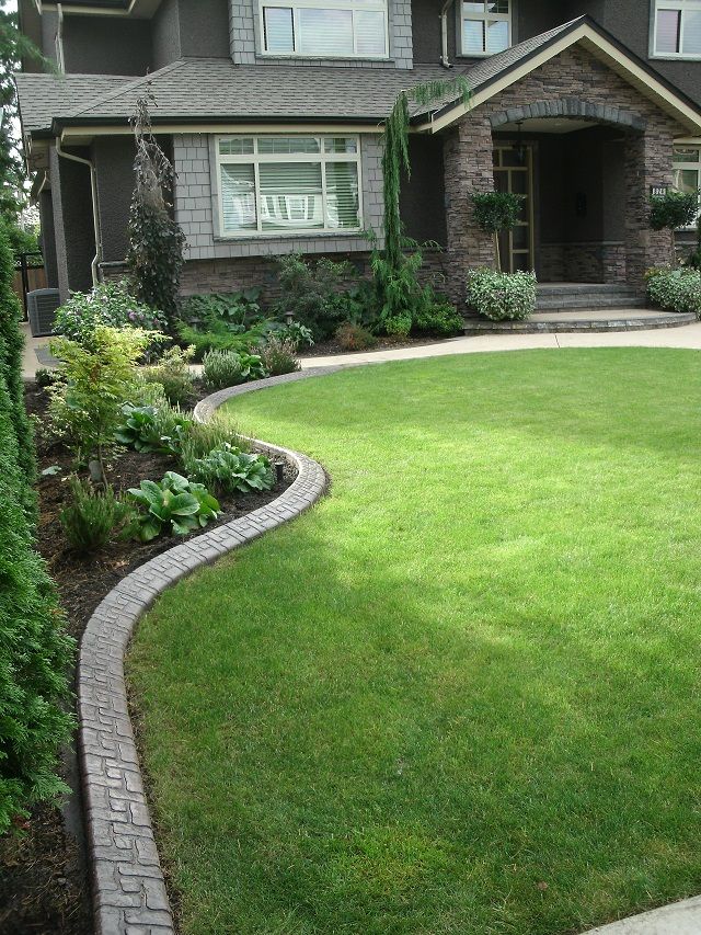
For the straight top and bottom rails I used 2×4 cedar, and for the curved rails I used 2×6 cedar. The balusters are 32” x ¾” round black aluminum deck railing.
I planned out the spacing and layout of everything. The space between the deck boards and the bottom rail is 3½”, which makes it easier to push snow off the deck but too small for a child to crawl under.
The top rail is 38½” above the deck to prevent anyone falling off the deck. The balusters are 4½” apart at center, which makes the space too small for an infant’s head to go through. The railings would look great and be safe.
To make the curved top and bottom rail, I made a cardboard template which included the baluster spacing. I used a 7¼” circular saw to cut the cedar 2x6s into curved rails.
Finally, I cut all the railing posts at 40½” above the deck boards, and the pergola posts at 100½”.
Assembling the railing was easier than the cutting and drilling, but went easier with a helper. I installed the bottom rails, put the balusters in place, then lined everything up and put the top rail on.
I then covered the cedar posts temporarily with tar paper until I purchased the caps. To prevent the bottom rail from sagging I cut and installed supports halfway between the posts.
Step 11: Build the Deck Stairs
To plan the stairs I determined the distance between the deck surface and the ground. It was 49”. The standard for stairs is a run of 10” for every 7” rise, so I’d need 6 step stringers for my stairs. The 7th step is from the top of the stringer to the deck.
I used two of the 3 pre-cut pressure treated 6 step stringers I’d purchased to determine where the bottom of the steps would sit. I manually dug 2 holes for stairs footings, slid in the 8” sonotubes, and filled them with concrete.
To attach the 4×4 cedar posts for the stair and railing support I used Simpson Strong-Tie 4×4 ZMAX Galvanized Adjustable Post Bases.
To make the stairs I used 5/4×6” cedar planks. I used 2 trimmed pieces to make the 9¼” for each of the stairs, and one plank for the riser.
This would provide space for water and snow melt to drip off the stairs. The riser also prevents a child from getting stuck between the stairs.
The 3 stringers were attached to the deck using galvanized adjustable stringer connectors. The middle stringer makes the stairs more rigid. The two outer stringers were attached to the posts with ½” hot dipped carriage bolts.
Simpson Strong-Tie 4×4 ZMAX Galvanized Adjustable Post Bases set into the concrete secure the railing posts.
Used 3 pre-cut pressure treated 6 stairs stringers attached to the rail posts with bolt.
Galvanized adjustable stringer connectors attach the stairs to the deck.
Stairs – 9 ¼ from trimmed 5/4×6” cedar planks. Raisers – 7 ¼ from 5/4×6” cedar planks
Take a moment to check out my article about different landing options for deck stairs.
Handrails
I used straight cedar 2x4s for the top and bottom rails and the ¾” round black aluminum for the balusters.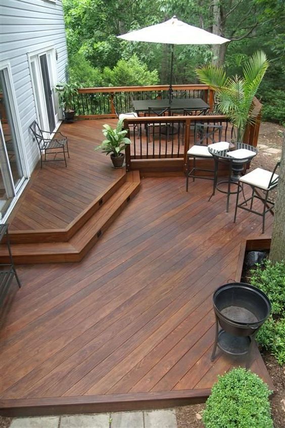 The spacing was kept the same, but the holes for the balusters were drilled on an angle. With 40 holes to drill on the same angle, you may want to make or buy a jig.
Conclusion
The deck is complete except for the pergola, but that’s another project. It looks awesome if I may say so myself, and is a great place to entertain and enjoy a relaxing BBQ.
My deck may also be considered freestanding since it is supported close to the house and by two beams; the ledger board isn’t load bearing. This may prove helpful in some areas due to local regulations.
Hopefully this guide has provided you with some useful information on how to build a deck. Your comments are appreciated.
If you know someone who is thinking about building a deck, share with them if you liked it. Remember, you don’t have to hire the professionals; you can plan, design and build it yourself. Are you up for the challenge?
Related posts:
5 Cheapest Decking Materials in 2022 Staining Deck vs Painting: Which Is Better? Deck Building Code Requirements
Eugene Sokol
Eugene has been a DIY enthusiast for most of his life and loves being creative while inspiring creativity in others.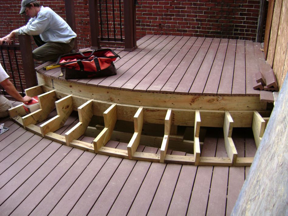 He is passionately interested in home improvement, renovation and woodworking.
First rank ship of the line Royal Willem. Euromodel model. Part 3
Tags: Euromodel, EU99006, battleship
Review. The third part. Start here
Velvets
The main velvet - between the lower cannon deck and the waterline - consists of three planks aligned in width, the middle velvet - of two combined ribs, and the velvet of 3-rib2 spaced channels , the lower of which in the nose repeats the line of the latrine platform. The location of the velvets on the body of the model is very important, because tied to the lines of cannon ports, quadeck galleries and latrine platform at the same time. The installation of velvet is carried out according to the scheme used to install the planks of the second skin, only the use of PVA glue in this case is considered the most justified.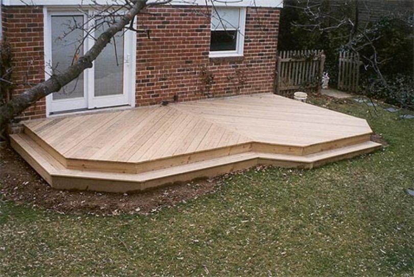 You should not even try to cut crossed cannon ports in velvets until the glue is completely dry (Fig. 30).
Fig. 30. Velvet and fenders.
Fenders
Four fenders per side were installed on the ship, which are also installed on the model. The fenders must be very carefully adjusted in accordance with the obstruction and bending of the sides in the appropriate places. To simplify the fitting of fenders, it is recommended to remove the bead profile with a cardboard template, and then transfer the required fender shape to a wooden blank. The fenders should be made slightly longer than the design ones, protruding above the gunwale with their subsequent adjustment to the bulwark railing.
Side ornament
Unlike the hull plating, when, in order to avoid curvature of the hull, the laths are laid simultaneously on two sides, the installation of the side ornament should be carried out exclusively alternately - first on one side, and then on the other.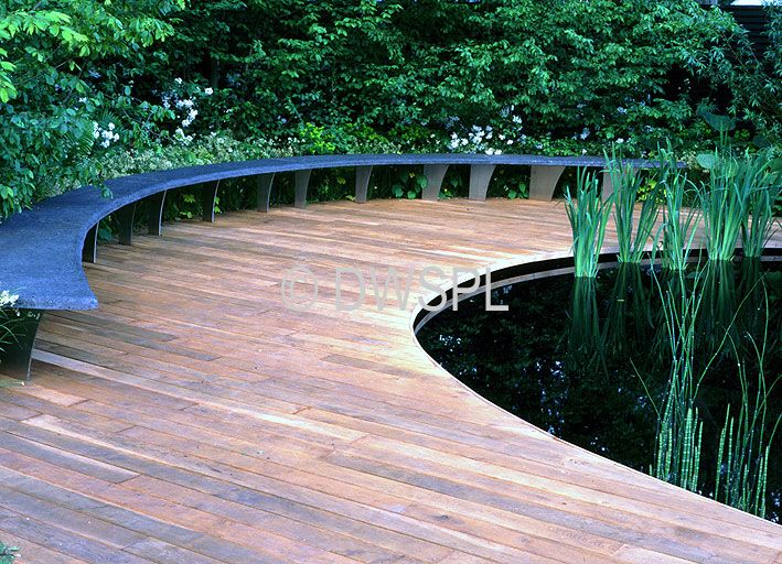 Properly installed relative to the cannon ports, the fenders are an ideal 'conductor', helping to set the ornamental elements exactly in their place. As before, the cast elements of the ornament of the set require little preparation and cleaning, however, one should be very careful not to oversize the small gaps in the ornament, possibly covered by casting bridges. The best tool for this job is a set of velvet files. Each element should be aligned at the ends for proper docking with neighboring ones, clean the back surface and glue in place with cyanoacrylic glue. Each subsequent section goes through the same procedure with the addition of a dry fit to the previous one. A possible problem, which is a negligible difference in thickness and manifests itself, however, in a conspicuous difference in the ornamental strip, can be solved by carefully removing this 'step' after the glue has dried.
Before installing each element of the ornament in place, make sure that openings are made in the appropriate places for the holes of the gun ports, because.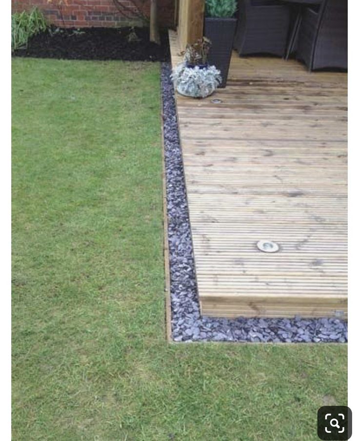 after gluing them into place, it will be almost impossible to do this.
After gluing all the details of the ornament, it is necessary to close the still visible joints between the elements with a suitable putty (Polyfilla is recommended), which can be rubbed into the joint with your finger. Larger inconsistencies are pre-corrected with needle files, followed by putty, which makes the joints almost invisible.
The installation of the ornament in the foredeck area should be prepared by marking the places for installing decorative elements in strict relation to the corresponding pairs of regels and crumbles, followed by fitting the decorative elements to the required size.
Oversized fenders and bulwarks can now be resized to match the top ornament line. All together, this is covered with a gunwale from a 4x0.5mm strip pre-curved in the design places of the bulwark drop (Fig. 31).
Fig. 31. Gunwale bulwark.
 Protruding fenders.
Ledgers
Luckily, the set comes with cast ledgers (Fig. 32), which, like wood, do not require preliminary bending, the shape and radii of which are simply terrible. But even in this case, this stage of work is so frighteningly significant that it is recommended to take it only in a good mood and on a good day.
Fig. 32. Cast crossbars.
However, all bolts need to be adjusted to the surface of the model body. This fitting is a long and careful work, which is best started from the thicker end, gradually and proportionately removing the excess material along the ledger or bending it until the required length is reached, and the thin end is cut and machined to the required shape.
All ledgers are pre-drilled for pin mounting and glued in place with epoxy (Figure 33). The rest, smaller and less load-bearing parts, and due to the impossibility of holding them in place while the epoxy glue is curing, are installed in their places with cyanoacrylic glue.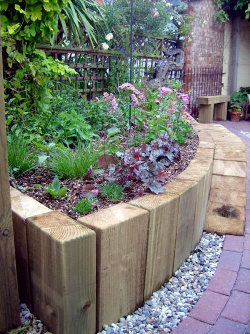
Fig. 33. Installation of crossbars.
After that, you need to fit the hole and the water-wooling bracket, paint the entire assembly from the inside and install the latrine grate.
Any gaps between the crossbars and the figurehead must be sanded and filled before final exterior painting.
Guardrails
The model is required to install more than a hundred 5mm height guardrail supports, cut and formed from a 5x1mm strip, glued to the gunwale strictly along the line of the railing. For the manufacture of these supports, it is best to make a simple jig that will ensure the identity of all blanks.
In most cases, the railings have a vertical bend at their ends, repeating the shape of the bend in this place of the side ornament. Therefore, it is recommended, firstly, to make the railing composite of two 4x0.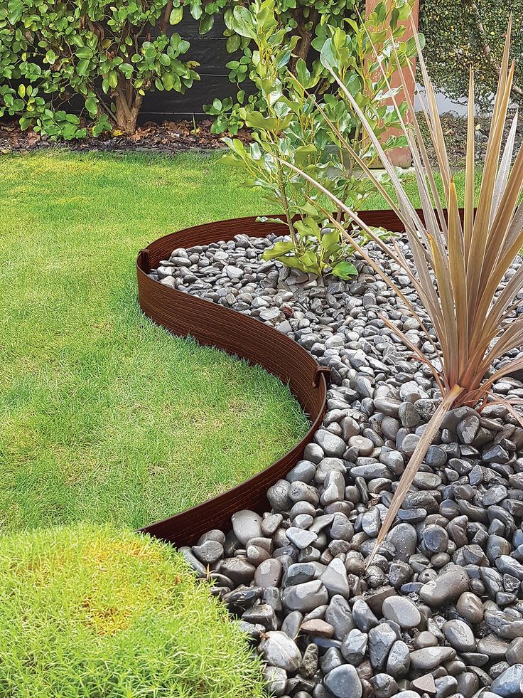 5mm strips, and secondly, to bend each of the railing blanks using a trimming tool or notch grooves along their inner side, after which these blanks are glued with PVA glue, holding them in the jig or even 'crocodiles' to hold the shape of the bend.
The fore-deck front guard, in contrast to the side guards, has a simpler, ordinary appearance and does not need comments.
Rusleni
Rusleni should be made and installed in pairs and at the same time for both sides in order to guarantee their identity. The inner ends of the channels must unconditionally repeat the shape of the sides in the appropriate places, which, among other things, will ensure the strength of the bonding to ensure resistance to sufficiently high loads that occur when the cables are stuffed. For the same purpose, several knees are installed on top of the channels in accordance with the drawings. The brackets must also be fitted very precisely to the bed and hull side to ensure the strength of the adhesive joints. Sufficient exposure should be given - at least a day - to dry the PVA glue used to connect these elements before starting further work on tying the channels.
Shrouds
The set comes with prefabricated shrouds, however, if we are strictly concerned with the quality of the parts, they are somewhat oversized. The lower yufers are inserted into the upper loop of shrouds, the lower end of which is inserted between the channel and its crossbar (Fig. 34). The end of the shroud is bent towards the hull, passes through the upper ring of the putens and is glued into the hole on the hull with epoxy glue. It is very important to mark these holes on the hull not only in relation to the line of the channel, but also at such a distance from each other that they allow the installation of shrouds and putens in line with the corresponding shrouds. To ensure the strength of this assembly, pins with a semicircular head are additionally installed in the lower holes of the putens.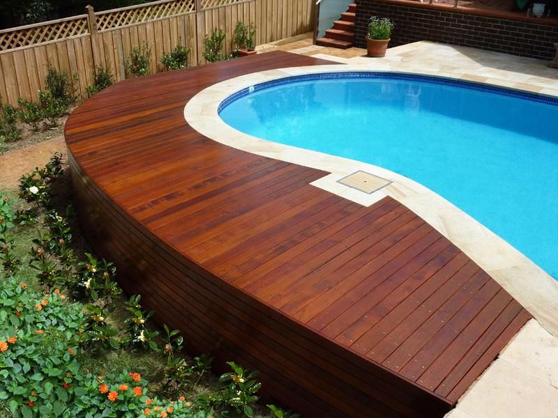
Fig. 34. Rusleni and vant-putens-ufers.
To facilitate work on the mizzen channels and due to the fact that these elements of the set are made somewhat sloppily - with a slight discrepancy in size, and also, in order not to lose small details in the process of work, it is recommended to put shrouds-putens-ufers on a drop of epoxy glue, paying attention to the correct position of the holes for the lanyard. The slightly larger shrouds of the main and foremasts are held somewhat more firmly in the shrouds, so they should not be glued for the convenience of subsequent tightening of the standing rigging.
Nasal decorations (forcastel)
Installing ornamental elements in the nose of the model 'in place' is rather complicated and may not lead to a quality result. The height of the surface on which it is required to work, and the fact that it is rather difficult to access, prompts the modeler to make the following decision: the entire assembly, including ornaments, semi-cylindrical places for looking ahead, etc.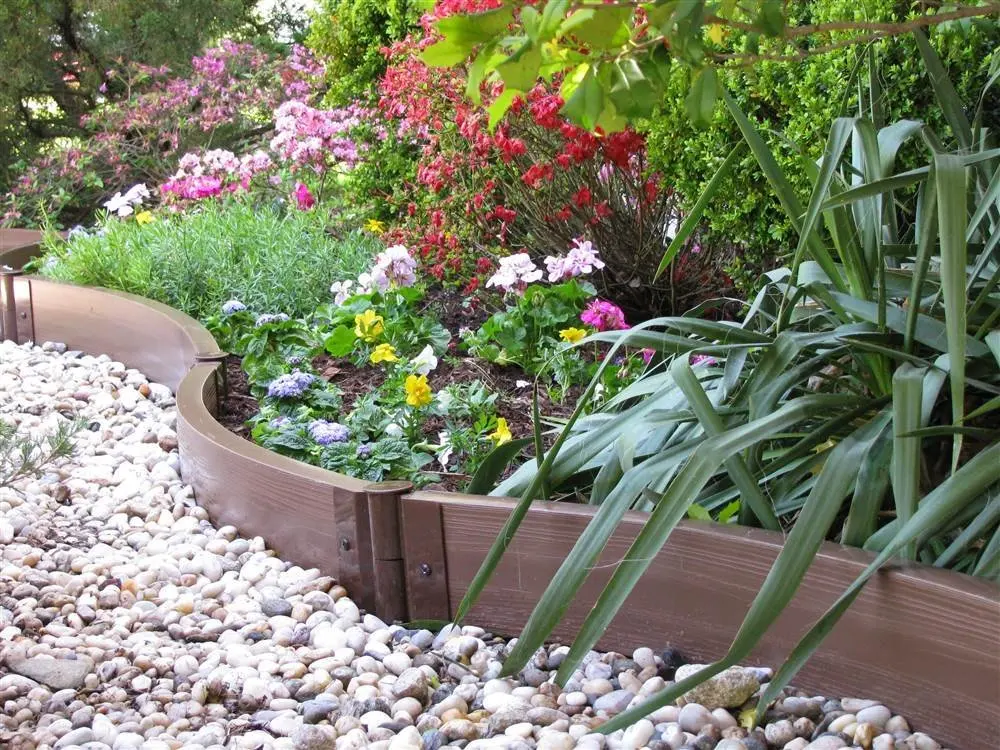 , should be carried out outside the model, on a false basis, which should be installed on own place.
The basis of such an assembly can be made of two layers of veneer, glued together to increase strength, like plywood, with mutually perpendicular fibers. The base is then adjusted to its place on the front wall of the case and the required elements are installed on it.
First of all, half-cylinders must be made, constantly checking that their size matches the size of the molded decoration elements applied on top of the front wall supplied with the set. After that, two cannon port covers and a central door are marked out, made and mounted, painted in black matte. For edging the ornament from strips 2 mm wide, moldings of the appropriate section are polished, which are painted in gold and, after drying, cut into the required size. After that, you can install the assembly in its proper place.
It's entirely possible that a modeller might have thinner and longer fingers or their own tried and tested method of working in cramped conditions, but the above method can be recommended not only to the average modeller, but for many other tasks, because it is much easier to redo a marriage made on a working table than the same, but installed on the model.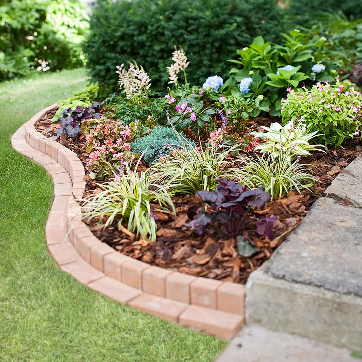
Now you can install the previously mentioned ornamental elements that cover the front wall of the housing from above in their places, remembering to paint them before installation (Fig. 35). With the correct, accurate performance of all work with constant checking and rechecking at each stage, the semi-cylindrical vertical inserts should be carefully 'covered', and an arch formed by cast elements will rise strictly above the central door. It should be remembered that the lower part of the ornamental details must be lightly sanded to repeat the convex profile of the deck, but this work is quite simple and should not raise any questions. To stick the ornament elements in place, it is recommended to use superglue gel.
Fig. 35. Bow decoration, semi-cylindrical lookout seats and edging of the front of the deck.
Helical ladders
The principle and sequence of manufacturing these left and right handed ladders is well illustrated in the drawings, however, the use of the correct and appropriate equipment and fixtures for the direct manufacture of ladders is at the mercy of the modeller. The first thing to consider, regardless of which method of manufacturing parts and assembly is chosen, it must ensure that several, and even mirror-turned, elements are absolutely identical. You should not even think and count on luck in assembling the 'eleven' micro-parts just with the hope that 'everything will work out' and the ladders will look as they should be - symmetrically.
It is proposed to follow the following procedure: first of all, two identical parallelepipeds are cut out of balsa according to the dimensions of a clean spiral ladder (Fig. 36). Both bars are given a curved shape. The symmetry of the blanks is constantly checked. The marked steps are cut out in any way available to the modeler. And again, 'by eye', the bars are checked for symmetry and, if necessary, polished. After that, vertical risers are mounted, and then the horizontal steps of the stairs themselves from a strip 0.5 mm thick, and the ends of these parts, after drying, are carefully polished to the level of the outer and inner curved surfaces of the block. After that, both bowstrings of the stairs are glued. During this work, quick-drying super glue is used to connect the parts, but even in this case, it is recommended to leave these parts overnight before continuing work, because the next step is to cut the balsa block flush with the bottom line of both bowstrings and even a little deeper. It is quite convenient to perform this work with an engraving tool and burs, although a quality result can be obtained using a suitable hand tool.
Fig. 36. Production of curved ladders.
Anchors and bitings
Due to the huge perceived load, the anchor biting posts pass through the main deck deep into the ship, where they are attached at several levels. However, the modeler can be so scrupulous not to adhere to such a degree of detail for the model under consideration and mount only the part of the anchor bits visible above the deck. An additional caveat: the blank of the biting racks that comes with the kit is not so good, so it should be put not only on glue, but also on a pin. Inserting the cross-beam and biting posts into a half-tree is not difficult, it is quite simple and can be fixed simply with glue.
Rudder
The kit includes a pre-cut rudder blade. Only careful marking of the hinge cutouts is required. It should be remembered that these cutouts must be large enough to allow you to bring the loops of the steering pen with baited pins and the loops on the body and then insert the pins into place.
If the modeller wishes to increase the detail of the rudder, please carefully examine fig. 37.
Fig. 37. Installing the steering wheel.
Note: The wooden lock is installed only in one place on the starboard side on the first loop above the waterline.
The handlebar hinges supplied in the kit are cast and very strong. They look great, but you have to be very careful with them, because if you bend them - primarily to follow the curve on the case - they can easily crack. The contact surfaces of the hinges are cleaned and the hinges themselves are mounted in place with epoxy glue. Super glue for this work should not be used, because. with it, the modeler will not be able to correct the position of the parts to be glued.
Ship Boats
This step is not as easy as you might expect with a boat hull blank included. Considerable work is required to fine-tune this blank so that it more or less looks like something worthwhile. First of all, you should pay attention to the gunwale line, which should be quite strongly curved (Fig. 38). When processing this curve, an excessive step is formed inside the boat hull, which must be removed. After that, the slates are laid on the bottom and the rest of the detailing is done inside the boat hull. Paddles are mounted.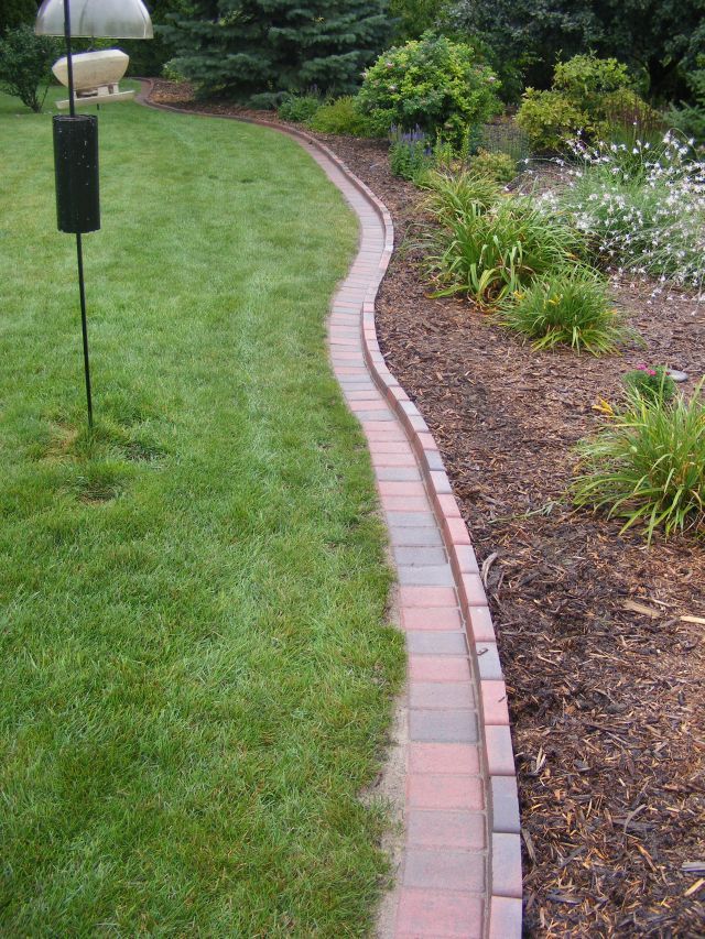
A finished keel groove on a workpiece is something with something, and only after significant labor costs a more or less worthy small boat is obtained (Fig. 39).
Fig. 38. Scheme of the ship launch.
Fig. 39. Ship launch.
Gun Frames
Basic assembly is made from the parts included in the kit: wheels, axles, sidewalls and barrels. However, depending on the desire of the modeler, there are many details that can be added to increase the realism of the ship's guns (Fig. 40). The drawings perfectly show the piping of the guns both to the deck and to the bulwark. This immediately necessitates the preparation and installation of the 144 small double blocks visible on the decks.
Fig. 40. Ship's gun and its harness.
they must be of different diameters on the front and rear axles. There are two types of gun frames in the set - larger and smaller, so, the small wheels of the first are equal in diameter to the large wheels of the second.
To install the smallest wheels, slightly grind the axles of the beds. You should pay attention to the fact that the axles do not turn out to be cone-shaped, because in this case you can easily turn the wheel. Drilling a hole in the wheel itself can also be dangerous.
Real wheels were fixed on the axles with special wedges, which, however, are quite difficult to reproduce on such a small scale model, however, in all cases, the axle should protrude beyond the surface of the wheel and - in no case! - must not be sunk.
Brass wire is supplied to simulate bolt heads. It should be remembered that before installing the cut pieces of this wire, it is necessary to grind their ends in order to remove the burr, which in all cases is formed either during cutting or cutting the wire.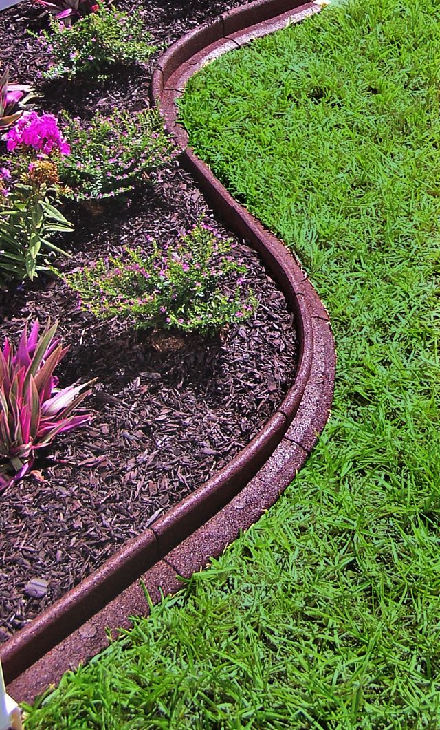
Wooden vertical aiming wedges, installed under the breech of the barrels, can be made from any suitable lath and glued into place. These wedges perform two useful functions: they allow you to set all the gun barrels at the same angle to the horizontal and act as a third reference point for gluing the same barrels.
In all cases, any desired degree of detailing of the guns must be done exactly at this stage, since later on the modeler simply will not physically be able to fix or mount anything on the guns due to lack of access to them.
Cannon Port Caps
Making these caps is not an easy task in itself and can, due to its size and importance, be a project in itself. The required total number of these elements, each of which consists of five parts, raises the question of the modeler on the correct preparation for this work in order to ensure their complete identity without exhausting and repeated measurements and markings.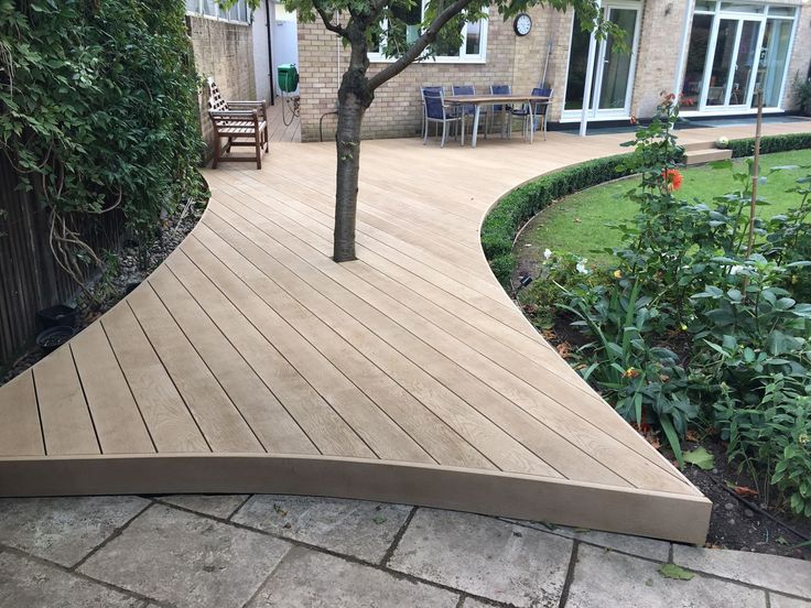
The outer side of the lid consists of two parts glued along the width, to which a third, square, slightly smaller part is glued from the inside. Initially, two selected wooden strips should be glued in width, which, after drying, are cut into pieces equal to the design width of the covers. Then the third, inner side is glued and pre-painted loops are mounted on super-glue. The inside and ends of the cannon port covers are painted matte red.
Two holes can be drilled at this point for each gun port in the body, into which the 'legs' of the molded gun port cover ornaments are inserted, although this work can be done later, but the actual fitting of the port covers into place - certainly - should not be done. at this stage, but significantly and as late as possible, so that in the process of further work on the model not to tear or damage these covers.
continued
Based on The Period Ship Handbook
Helipads, swimming pools, winter gardens and wine cellars on Monaco Yacht Show
- Forbes Life
- Ivanova Irina Author
Forbes Life visited the Monaco Yacht Show and talked about the new yachts launched this year, in the construction of which their creators used innovative technologies
Every autumn, the Port of Hercules hosts a yacht show under the patronage of Prince Albert II of Monaco, showcasing the pinnacle of design, technology and luxury available to super-wealthy sailors. This year, 125 yachts and 600 companies participated in the Monaco Yacht Show. 44 yachts were shown for the first time. The largest yacht reached 111 meters, and the average length of the exhibits was 50 meters. The total value of the superyachts exhibited in Monaco is $4.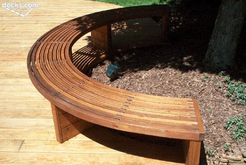 3 billion. Shipyards building megayachts are loaded to capacity. At the same time, sales of new-build projects noticeably lag behind the previous year. Shipyard representatives note that the audience of buyers has rejuvenated, and some of them are purchasing very large yachts. There has been another trend that is not typical for a stable (in the economic and political sense) market - the sale of actually new large yachts, which are barely a year and a half old, and their number is growing.
Shipbuilders are increasingly turning to the theme of green ecology as customers increasingly want to travel to remote locations with a unique ecosystem. Experienced shipowners are setting the tone for the industry by challenging shipyards to create innovations never before seen.
Russian clients have been the key to the huge growth of the superyacht industry since 2000, according to the latest figures from SYT Intellengent, a marketing agency dedicated to yachting market research. Russians are still valuable customers, especially in higher market segments, where their share is 11%. However, North American clients have remained a driving force in the market over the past few years, buying 17% of superyachts under construction.
Yacht building is considered one of the fastest growing industries. Forbes Life, having visited the MYS exhibition, included in the review only the newest yachts launched this year, during the construction of which innovative technologies were applied.
LurssenTIS
Length: 111 meters
Built: 2019
Shipyard: Lurssen, Germany
Design: Winch Design0005
When you first step on board this vessel with a breathtaking interior, the feeling that the yacht is Russian does not leave.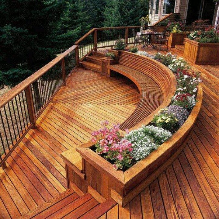 Or Ukrainian. There is so much palatial and pompous, refined and incredible, filigree and grandiose in it. A grand white marble staircase leads up to the upper deck from the main saloon with twisted gilded steel ornamentation. Each of the 8 guest suites is themed after unique geographical regions from around the world: Provence, China, Tuscany and even a Russian dacha.
Another feature rarely seen on board is the fireplace. Water vapor and lighting effects cleverly mimic the look of an open fire, radiating a warm, gentle glow. The marble edging is carved to match the overall décor, including repetitive leaf motifs and harking back to the days of Kings Louis XV and XIV. The citrus theme will accompany you to the spa. The relaxation area, which centrally connects massage parlors, aromatherapy showers and hammam, features a curved molded ceiling with handmade citrus fruits that looks like a three-dimensional lemon grove from the island of Capri.
Some interior details are reminiscent of the yard's 85m Solandge built in 2013, but why does everything about this new yacht feel over the top?
On the main deck, the lobby leads to the office and then to the dining room through a mirrored vault that can store 200 bottles of wine.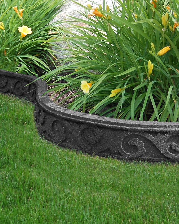 Mirrored walls give the impression of an infinitely expanding space, while architectural lighting bounces off polished stainless steel, adding volume and light to the wine cellar. Each bottle holder has a marine fastener, and the cellar holds wine bottles of all sizes.
The helicopter can land on the mega yacht on two platforms: the bow is reinforced for intermittent takeoff and landing (touch-and-go), and the upper deck aft is designed for more frequent operation of a Eurocopter EC135 size helicopter. When not in use, this deck serves as a dance floor and open-air cinema.
The yacht can be chartered in any season. Cost per week - only $2.2 million
Awards: Winner of the Monaco Yacht Show 2019 in the nomination "Best Interior Design".
More than 170 different finishes for the interior. Special, custom art panels on walls, ceilings and concealed TVs are used throughout to wow guests.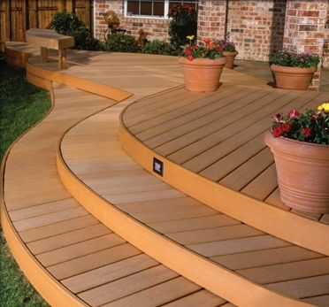 Swarovski crystal ceilings in the spa. Dressing tables, massive decorative coasters and shelves with hand-laid semi-precious stones can be seen throughout the yacht. Floors in natural wood and limestone, fashion items, decor and cabinets made of semi-precious stones, exotic woods, parchment, leather and mother-of-pearl: everything is in harmony, avoiding the boredom of uniformity.
Sun deck over 30 m long and over 250 sq. m. never seen before on ships of this size. Jacuzzi for 8 people with indoor informal dining area and swimming pool on the main aft deck. This area can be easily transformed into an al fresco cinema with a 4-meter screen.
SilverYachtsBold
Length: 85 meters
Built: 2019
Shipyard: SilverYachts, Australia
Design: Espen Oeino (exterior), Vain Interiors (interior)
Looking at this 85-meter military-style vessel with a huge helipad, you will not immediately believe that this is not a warship, but a luxury yacht.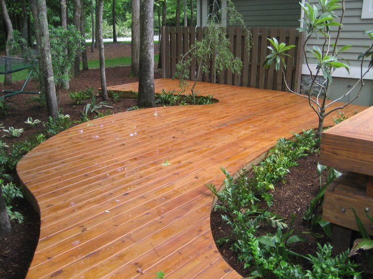 Perhaps one of the goals of its creation was to shock the public - a success for the famous designer Espen Oino.
The Megayacht is built on a new generation platform, carefully analyzed and tested in advance to create the most efficient hull shape in terms of engine power per tonne of displacement. As a result, with two compact MTU 16V 4000 M73L engines with a power of 2880 kW each, this behemoth can reach speeds of up to 24 knots. The draft of 2.7 m is unique for ships of this size, which allows the vessel to go to shallow depths.
Inside everything that is inherent in luxury superyachts - 8 cabins for 18 guests, a sky lounge of 300 square meters. m with floor-to-ceiling windows 3.75 m high, a dance floor, a glazed conservatory, a jacuzzi pool on the deck for 8 people. The interior decoration includes teak, oak, marble and metallic fabrics. A certified helipad with a 3000 l fuel storage hangar allows you to travel on board with an Agusta Westland AW109 type helicopter.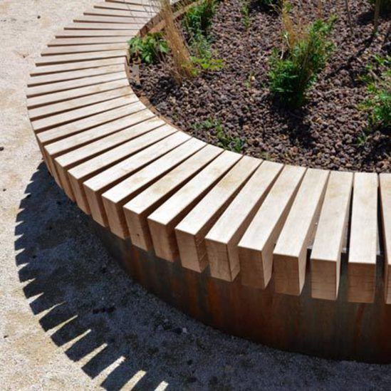 To date, this is the largest yacht built in Australia.
Excellence
Length: 80 meters
Building: 2019
Verf: ABEKING & RASMUSSEN, Germany
Other on the roadstead, this unusually shaped vessel gathered a mass of spectators who were perplexed in conjectures - is it a submarine, a spaceship, or the closest relative of the famous motor yacht "A"? As conceived by the customer, an experienced yachtsman, his new brainchild was supposed to evoke just such emotions - to surprise. Let them argue whether they like it or not, but no one will remain indifferent.
In addition to its extraordinary body lines, another unique and sophisticated feature that makes the Excellence stand out from the crowd is its curved mirror glass exterior.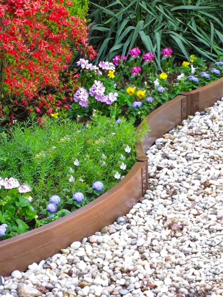 It was not easy for Abeking & Rasmussen. Glass consists of 4-6 panels; complete with insulating layers and finishes, they are 7-8 cm thick. The mirrored exterior had to withstand the expansion and contraction of the aluminum superstructure and the vibrations caused by the movements of the yacht. Never before had glass panels of this height been installed on yachts. However, the biggest challenge was that the glass had to be as hard as possible on the outside, so as not to distort the mirror surface and perfectly reflect the Excellence's surrounding landscape. Also a technical challenge was the design and development of electric shutters, which became thinner with height due to the special rounded shape of the window. Many versions have been created and tested thousands of times to ensure the durability of the design. The result is roller shutters that emerge from a hidden area in the floor. The exterior doors also had to be designed to accommodate the slope and curvature of the superstructure.
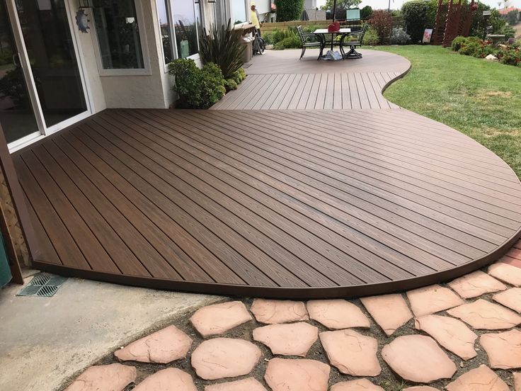 Each door uses a slightly different mechanism, swinging silently open and sliding over a curved support.
Equally impressive is the interior of the megayacht with its two-story atrium-like foyer, with massive frameless glass panels that create an unforgettable experience and unique views. This yacht offers more than expected. Inside, guests can expect luxury in saloons and staterooms. A large swimming pool is on the main deck aft, a jacuzzi on the owner's deck and a garage at water level where the limousine tenders will be stored. “Excellence represents a huge milestone,” says designer Andrew Winch. “A completely unique add-on, it signifies an innovative and exciting new genre for Winch Design.”
The interior features trendy new materials, such as precious silver strands woven into the composite to create the illusion of metallic carbon fiber, and interior trim heavily inspired by classic cars. This is not surprising, because, according to the American Forbes, the owner of Excellence is billionaire Herbert Chambers, the owner of the Herb Chambers company of the same name, one of the largest automotive dealer groups in the United States.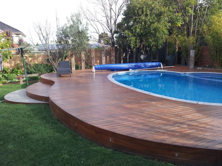 This is not the first yacht to bear the Excellence name, boats from an expensive hobby have become part of his business. He builds and rents yachts for charter.
Artefact is the first DC bus hybrid superyacht with batteries and ABB Pod variable speed propulsion system. This new system offers higher efficiency and lower emissions as well as reduced noise and vibration levels. Together with an advanced dynamic positioning system, this hybrid superyacht can hold its position even without using an anchor, protecting the sensitive seabed.
A significant portion of the exterior, designed by Gregory Marshall, features a unique 740 sq. m, including the central section from floor to ceiling. However, glass weighing 60 tons is not a yachting achievement, usually a quarter-foot (7.6 cm) marble and wood trim is used to lighten the vessel. However, on this vessel, a lightweight composite (rather than aluminium) superstructure made it possible to use such heavy glass windows for luxurious sea views.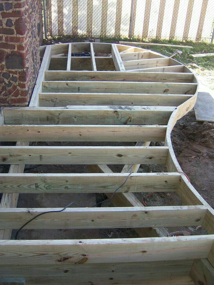
Technical innovation - a 7-meter mosaic pool on the 6th deck, turning into a jacuzzi and a niche in the form of a grotto; a waterfall separates them, creating a natural privacy zone.
Total size and weight of the pool, holding approx. 20 cu. m of water, turned out to be a difficult task for the designers. The pool is partially recessed into the deck to create the desired depth of 1.2 m and minimize external influences, the waterfall is additionally protected from side winds by the walls of the grotto.
The water level can be changed to swim in the pool during rough seas. These are not such big compromises to get the best views from 12 meters high.
The master suite bathroom has a floor-to-ceiling window overlooking the sea and a wall with a rare mosaic of cut natural tree trunks.
600 sq. m of al-fresco outdoor decks, including a solarium with hot tub and indoor gym; club with spa, bar and sauna is 65 sq.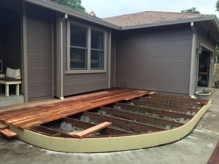 m. The superyacht was put up for sale in the spring before launching for €87.5 million. According to the captain who oversaw the construction process, the sale is connected with the birth of a third child in the owner’s family - a yacht with two children’s cabins (and there are 7 in total) simply became small . The price was lowered twice - in October it already costs €7
The new Enhanced Fast Displacement (FDHF) hull features to increase efficiency at a design maximum speed of 30 knots and reduce fuel consumption at an economical cruising speed of over 20 knots. The new technologies applied in the construction of Cosmos make it possible to say that she will be the largest and fastest aluminum motor yacht with a traditional propulsion system in the world. For comparison, imagine a 263-foot sports car on the water. The main feature of the exterior from Winch Design is a 3,000 sq. ft., which can be used as a heliport capable of receiving a Eurocopter EC135, or transform into a giant dance floor, a 24-foot glass-bottomed pool and a beach club with a sunken bar.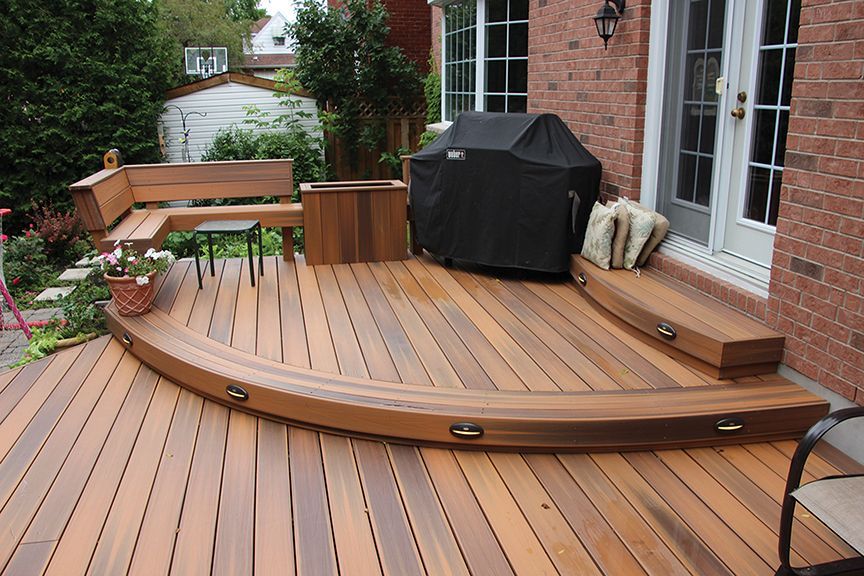
Dutch design studio Sinot approached the interior in an unusual way, using elements inspired by nature, including large windows, backlit onyx, crystal glass panels, straw marquetry, silk rugs and leather wall panels. Cosmos has a large spiral staircase that wraps around a glass elevator that spans four decks.
FincantieriVIS
Length: 80.8 meters
Shipyard: Fincantieri, Italy
Design: Fincantieri Yachts and Francesco Paszkowski
At the Monaco Yacht Show, Fincantieri Group's private megayacht building division unveiled the new generation concept -VIS. According to the shipyard itself, VIS is a completely innovative project based on the metamorphosis of one of the main activities of the Italian shipyard Fincantieri - the design of modern warships.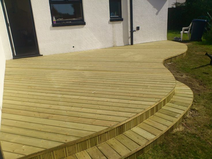 The group builds for the Italian Navy. Even the name of the project is sharp and energetic, meaning “strength” in Latin. Apparently, the time is such, your house should be your fortress, and all the beauties should be hidden from prying eyes.
That is why the ship uses sophisticated architectural solutions along with cutting-edge technology. In an instant, an austere ship turns into a yacht with lounge areas, a beach club, reclining terraces with panoramic views, a swimming pool with a cascading fountain covered with honeycomb solar panels, creating not only a masterpiece of modern design, but also performing the function of additional autonomy and environmental friendliness . A huge helipad is certified, which allows you to move on board with a fairly heavy helicopter. The concept was developed by Fincantieri Yachts in partnership with Francesco Paszkowski's studio. Since 2005, when the company entered the yachting business, it has built (by the way, for Russian customers) the 134-meter "Serene" (2011) and the 140-meter "Ocean Victory" (2014), which have become popular not only because of the non-standard design and style, but because of the high reliability and quality of the ships.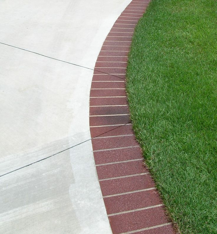 Actually, this is not surprising, the company has 230 years behind it in the field of shipbuilding.
Sultan
Length: 200 meters
Design: Pierrejean design
Jacques Pierrejean, the owner of the French studio Pierrejean, can be called one of the founders of modern aircraft interior design, and his company, for its vast experience and innovative models, can be called a research laboratory. He has worked with Falcon, Airbus, Boeing. His clients included Jacques Chirac, Spanish King Juan Carlos I, Italian Prime Minister Silvio Berlusconi and many other famous people. For more than 35 years, the studio has been developing classic interiors for sailing yachts, and is also known for its futuristic projects in the world of motor yachts, of which only 2 were realized. This time in Monaco, the designers presented their new eco-concept - the 200-meter Sultan hybrid trimaran.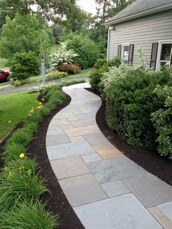
Special emphasis in the design of the ship - not only in technological innovation and comfort on board, but also in minimizing the impact on the marine environment. For this, it is planned to use a hybrid installation with a DC bus, batteries and an Electric ABB Pod propulsion system. This new system has already been implemented on the Artefact described above and offers improved efficiency as well as lower emissions and lower levels of noise and vibration. Using the dynamic positioning mechanism, a 200 m long trimaran will be able to maintain its position without the use of an anchor.
The incredible appearance of the gigayaha will definitely attract attention and, most likely, will cause a lot of controversy. On the aft deck, the Sultan offers two helipads for owners and guests. In addition to the standard set - swimming pools, gyms, dance floors, cinemas and spas, it is planned to create an art gallery and an oasis on the main deck - a garden with flowers, small trees and vegetables.